Welcome back to Vision Vitals. In this episode, we’re looking at a problem that often slips into Time-of-Flight imaging when scenes contain reflective or complex structures.
It is commonly known as multi-path interference.
Instead of returning through a clean, single route, the emitted light can bounce around the scene and reach the sensor from several directions, which pushes the depth engine toward misleading results.
As always, our imaging expert is with us to explain why this happens and the most viable approaches that are used to reduce its impact.
Glad to be here and looking forward to getting into this.
Speaker:
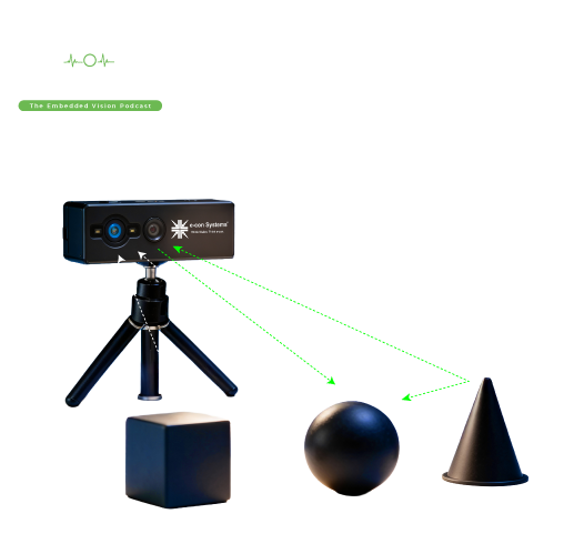
Multi-path interference happens when the light emitted from a ToF camera reaches a pixel through more than one route. Instead of bouncing once off a surface and returning directly, the light may scatter, reflect across several surfaces, or follow an indirect route before coming back.
The camera measures time-of-flight based on that returned signal. When multiple paths overlap, the depth calculation becomes inaccurate.
The sensor blends these signals and produces a value that does not represent the true distance. In a 3D point cloud, this appears as distorted points, misplaced geometry, or areas where surfaces seem to stretch or shift. The problem is most visible near reflective materials, shiny objects, glass, curved surfaces, and corners where light can easily spread and bounce.
Host:
Why does this interference occur? Walk us through the main causes.
Speaker:
Several conditions make multi-path interference more likely. The two major factors are:
Corners and structural complexity
Corners cause the emitted light to bounce across several edges before returning. A corner may produce two or more valid paths, none of which represent the straight-line distance the system expects. This creates depth shifts and irregular edges.
Large incident angle
If the light hits a surface at a steep angle, more rays tend to bounce away and strike other surfaces. These secondary reflections find their way back to the camera and interfere with the intended direct path.
All these scenarios push light into unintended trajectories, which leads to depth values that drift away from the physical layout.
Host:
How does multi-path interference show up in real depth data? What should people look for?
Speaker:
Engineers will usually see:
- Depth distortion: Surfaces may appear bulged, recessed or uneven, even when the actual geometry is flat.
- Patchy depth jumps: Adjacent points can show abrupt changes because each pixel receives a different mix of direct and indirect light.
- Incorrect shape outlines: Corners may appear rounded or misaligned because the sensor calculates depth from misleading phase information.
- Unstable results across frames: If the path reflections change slightly as the camera or scene moves, depth stability drops.
The interference does not look random. It has patterns tied to how light spreads across surfaces, so it clusters around edges, shiny zones, or complex objects.
Host:
Given how disruptive this can be, what approaches help reduce multi-path interference?
Speaker:
There are many methods to minimize the multi-path interference, and each targets a different part of the ToF process.
Different modulation frequencies
Switching between frequencies or evaluating depth across multiple frequency ranges helps distinguish true signals from misleading ones. Indirect paths tend to exhibit different phase behavior. Comparing frequencies helps isolate the direct path.
Advanced signal processing and algorithms
Algorithms can detect inconsistencies in phase or amplitude and remove values that fall outside predictable patterns. These filters analyze pixel performance across the neighborhood and suppress results that deviate from expected depth transitions.
This approach corrects many interference zones and improves overall depth reliability.
Spatial filtering techniques
Filters can smooth sudden depth spikes, reinforce continuity, and discard irregular depth points caused by indirect reflections. The goal is to maintain structural consistency while removing noisy outliers.
Material and scene-based adjustments
Avoiding highly reflective areas or altering the placement of shiny surfaces can substantially reduce interference. Even small changes in angle, orientation, or surface treatment can help because they alter the paths that scattered light can take.
Sensor placement and camera orientation
Simply shifting the camera by a few degrees or adjusting the height or angle changes how the light reaches corners and reflective zones. This reduces multi-path pathways before they even form.
Optical design improvements
Lens configurations can be optimized to minimize how much indirect light reaches the sensor. In some ToF designs, controlled apertures or refined optical stacks prevent scattered rays from hitting the pixel array.
Host:
How do reflective materials specifically influence the severity of this phenomenon?
Speaker:
Reflective surfaces create more unpredictable secondary reflections. Instead of a weak indirect signal, these surfaces send bright, well-defined reflections toward multiple parts of the scene. The sensor receives them almost as impactful as the direct return.
This makes the depth engine choose the wrong phase information, causing entire regions to appear shifted or warped. It’s especially noticeable near metallic objects, polished corners, or any surface with high specular properties.
The stronger the secondary reflection, the harder it becomes for the camera to isolate the correct path.
Host:
Are there scenarios where multi-path interference naturally stays low?
Speaker:
Yes. Scenes made of rough or diffuse materials tend to return a clean, predictable reflection. These surfaces absorb more light and send back a less complex pattern of scattered rays.
Environments with fewer corners, fewer reflective zones, and simpler geometry also reduce the number of available indirect paths. The more uniform the scene, the more stable the depth output from a ToF camera.
Host:
For those looking to reduce multi-path interference in production systems, what’s the best way to approach it?
Speaker
The best approach is to treat this as a multi-layer problem:
- Start with optical or placement adjustments to remove the most disruptive reflection paths from the environment
- Apply algorithmic filtering to suppress residual interference signals
- Use multiple frequency strategies if available, since they help distinguish genuine returns from misleading ones
- Evaluate scene composition, especially material choices, to limit reflective hotspots
Most deployments combine several of these methods since each step reduces a different part of the interference chain.
Host
And that brings the curtains down on today’s episode of Vision Vitals. Multi-path interference may form naturally in Time-of-Flight imaging, but with the right approach, it becomes a manageable challenge.
Understanding how indirect paths form and learning how to restrict or filter them helps build systems that deliver true depth values.
e-con Systems offers a wide range of Time-of-Flight camera solutions, and an upcoming addition to this portfolio is the AF0130-based 1MP 3D Continuous wave iToF camera, featuring on-camera depth computation, support for depth ranges of 0.2 m to 2 m and 0.5 m to 6 m, multi-camera interference mitigation, and compatibility with NVIDIA® Jetson platforms.
If you need expert insights for evaluating ToF cameras, please write to www.e-consystems.com.
If you need expert insights for evaluating ToF cameras, please write to
Close Full Transcript


 Mr. Thomas Yoon
 +82-10-5380-0313