Operating CF in UDMA Mode in WinCE using IDE interface through IDE to CF adapter
|
| by Z.Salim Javed |
| |
Abstract
|
| In many Wince devices Compact Flash (CF) cards are used through IDE (ATA) interface by using IDE to CF adapter.
CF cards are available in PIO mode and Ultra DMA mode (UDMA). There are lot of enquiries from various windows ce development newsgroups and mailing lists about the CF card not working or the Ultra DMA mode not working in Windows CE. Sometimes the problems
are there in the IDE to CF adapter card or in the software driver. Being a part of windows ce device driver and Windows CE BSP Development team we address these issues and help the developers to make work of CF in ultra DMA mode using IDE to CF adapter with this article. |
CF Card Revisions
|
| Compact Flash defines a physical interface which is smaller but electrically identical to the ATA interface. That is, it appears to the host device
as if it were a hard disk. The CF device contains an ATA controller. There are different revisions of CF cards available. Revision 2.0, revision 3.0 and
revision 4.0 will work in Ultra DMA16 (Speed 16MB/s), Ultra DMA66 (Speed 66MB/s) and Ultra DMA133 (Speed 133MB/s) mode respectively. PIO mode supports up
to 25 MB/s. All the revisions have backward capability. |
CF Card Device Information
|
| Each CF card revision details, sectors, cylinders, PIO mode support, DMA support details are available in the device information memory.
This information is read using "Identify Device" Command. The following is the register that defines the PIO and DMA specifications. |
| |
| Word Address |
Default Value |
Data Field |
| 49 |
0h |
Capabilities |
| 53 |
000Xh |
Field Validity |
| 64 |
00XXh |
Advanced PIO Modes Supported |
| 88 |
XXXXh |
Ultra DMA (UDMA) mode supported and selected |
|
| |
| In the Word 49 - Bit 9 and 8: |
| |
| Bit 9: LBA supported |
|
| |
Bit 9 shall be set to 1, indicating that this Compact Flash Storage Card supports LBA mode addressing. CF devices shall support LBA addressing. |
|
| Bit 8: DMA Supported |
| |
If bit 8 is set to 1 then Read DMA and Write DMA commands are supported. |
| |
If bit 8 is set to 0, then Read DMA and Write DMA commands are not supported. |
|
| |
| Word 64: |
| |
| Bits 7 through 2 are reserved. |
| |
Bit 0, if set to one, indicates that the Compact Flash Storage Card supports PIO mode 3. |
| |
Bit 1, if set to one, indicates that the Compact Flash Storage Card supports PIO mode 4. |
|
| If bit 1 of word 53 is set to 1, the values in words 64 through 70 are valid. If this bit is cleared to 0, the values reported in words 64-70 are not valid. Any Compact Flash Storage Card that supports PIO mode 3 or above shall set bit 1 of word 53 to one and support the fields contained in words 64 through 70. |
| |
| Word 88: |
| |
Bit 15: Reserved.
Bit 14: 1 = Ultra DMA mode 6 is selected 0 = Ultra DMA mode 6 is not selected.
Bit 13: 1 = Ultra DMA mode 5 is selected 0 = Ultra DMA mode 5 is not selected.
Bit 12: 1 = Ultra DMA mode 4 is selected 0 = Ultra DMA mode 4 is not selected.
Bit 11: 1 = Ultra DMA mode 3 is selected 0 = Ultra DMA mode 3 is not selected.
Bit 10: 1 = Ultra DMA mode 2 is selected 0 = Ultra DMA mode 2 is not selected.
Bit 9: 1 = Ultra DMA mode 1 is selected 0 = Ultra DMA mode 1 is not selected.
Bit 8: 1 = Ultra DMA mode 0 is selected 0 = Ultra DMA mode 0 is not selected.
Bit 7: Reserved.
Bit 6: 1 = Ultra DMA mode 6 and below are supported. Bits 0-5 shall be set to 1.
Bit 5: 1 = Ultra DMA mode 5 and below are supported. Bits 0-4 shall be set to 1.
Bit 4: 1 = Ultra DMA mode 4 and below are supported. Bits 0-3 shall be set to 1.
Bit 3: 1 = Ultra DMA mode 3 and below are supported, Bits 0-2 shall be set to 1.
Bit 2: 1 = Ultra DMA mode 2 and below are supported. Bits 0-1 shall be set to 1.
Bit 1: 1 = Ultra DMA mode 1 and below are supported. Bit 0 shall be set to 1.
Bit 0: 1 = Ultra DMA mode 0 is supported. |
| Bit 2 shall be set to 1 indicating that word 88 is valid and reflects the supported True IDE UDMA transfer modes: |
| |
| From the above register it is possible to know the mode of transfer supported by the CF card. |
 |
CF and IDE Pins Layout
|
| There are 50 pins in CF where as in IDE 40 pins so, it is important to check the pins mapping. |
| |
| Pin |
CF Pins |
IDE to CF Adapter Pins |
Pin Type |
| 1 |
GND |
- |
- |
| 2 |
D03 |
- |
I/0 |
| 3 |
D04 |
- |
I/0 |
| 4 |
D05 |
- |
I/0 |
| 5 |
D06 |
D06 |
I/0 |
| 6 |
D07 |
D07 |
I/0 |
| 7 |
CS0 |
CS0 |
I |
| 8 |
A10 |
- |
I |
| 9 |
-0E |
ATASEL |
I |
| 10 |
A09 |
- |
I |
| 11 |
A08 |
- |
I |
| 12 |
A07 |
- |
I |
| 13 |
Vcc |
Vcc |
- |
| 14 |
A06 |
- |
I |
| 15 |
A05 |
- |
I |
| 16 |
A04 |
- |
I |
| 17 |
A03 |
- |
I |
| 18 |
A02 |
A02 |
I |
| 19 |
A01 |
A01 |
I |
| 20 |
A00 |
A00 |
I |
| 21 |
D00 |
D00 |
I/O |
| 22 |
D01 |
D01 |
I/O |
| 23 |
D02 |
D02 |
I/O |
| 24 |
WP |
- |
O |
| 25 |
0 |
GND |
O |
| 26 |
0 |
GND |
O |
| 27 |
D11 |
D11 |
I/O |
| 28 |
D12 |
D12 |
I/O |
| 29 |
D13 |
D13 |
I/O |
| 30 |
D14 |
D14 |
I/O |
| 31 |
D15 |
D15 |
I/O |
| 32 |
0 |
CS1 |
I |
| 33 |
-VS1 |
- |
O |
| 34 |
-IORD |
-IORD |
I |
| 35 |
-IOWR |
-IOWR |
I |
| 36 |
-WE |
- |
I |
| 37 |
Ready |
IRQ |
O |
| 38 |
Vcc |
- |
- |
| 39 |
-CSEL |
-CSEL |
I |
| 40 |
-VS2 |
- |
O |
| 41 |
RESET |
RESET |
I |
| 42 |
-WAIT |
IOCHRDY |
O |
| 43 |
-INPACK |
DMARQ |
O |
| 44 |
-REG |
DMACK |
I |
| 45 |
BVD2 |
- |
O |
| 46 |
BVD1 |
DMA Detect |
O |
| 47 |
D08 |
D08 |
I/O |
| 48 |
D09 |
- |
I/O |
| 49 |
D10 |
- |
I/O |
| 50 |
GND |
GND |
- |
| |
|
|
|
|
| |
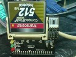
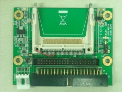
| In many IDE to CF adapter, mapping of DMARQ and DMACK are not done. These adapters will support only PIO mode, irrespective of CF card type. UDMA supported CF cards will not work in Windows CE 5.0 and Windows CE 6.0 if these IDE to CF adapters are used. Only PIO mode supported CF cards will work using these IDE to CF adapters. DMA supported IDE to CF cards are also available. |
| |
Ultra DMA Hardware Requirement
|
- Operation in Ultra DMA mode requires a crosstalk suppressing cable. The IDE to CF adapter shall have a grounded line between each signal line.
- Series termination resistors are required for the pins IORD, IOWR, CS, A00, A01, A02, DMAC, DACK, D0 to D15 and IORDY on both the host (Board) and on the IDE to CF adapter cards for operation in any of the Ultra DMA modes.
|
| |
Windows CE ATAPI driver
|
|
| In many cases Ultra DMA (UDMA) supported CF cards are not working, this is due to the IDE to CF adapter and a small fix in
software was introduced to make it work in PIO mode. Windows CE provides driver that works in PIO and UDMA mode.
When the ATAPI driver loads, it will read the CF card device information. These information's are used to decide in which mode
(PIO or DMA) the ATAPI driver should load. |
| If the device information states that CF card supports UDMA mode, ATAPI driver starts issuing the DMA commands.
ATAPI driver will fail if the IDE to CF adapter doesn't support the DMA pins and should start trying the PIO mode.
Normally it doesn't and hence the driver stops working. To make the driver work in PIO mode, the following fix was
introduced to indicate the driver that the CF card supports only PIO so that the ATAPI driver will work in PIO mode. |
|
m_Id.DoubleWordIo = 0;
m_Id.Capabilities &= (~0x0100);
m_Id.SingleDmaModesSupported = 0;
m_Id.SingleDmaTransferActive = 0;
m_Id.MultiDmaModesSupported = 0;
m_Id.MultiDmaTransferActive = 0;
m_Id.TranslationFieldsValid &= (~0x0002);
m_Id.TranslationFieldsValid &= (~0x0004);
m_Id.TranslationFieldsValid &= (~IDENTIFY_CAPABILITIES_IOREADY_SUPPORTED);
|
| |
| Usage of internal transceiver is preferred to save real estate and Bill of Material cost. |
| The Internal non-OTG transceiver needs to be used to get differential host signals from PXA320. This can be implemented using UP2OCR register with HXOE =1; HXS = 1; SEOS = 0 and also enabling pull downs for D+ and D- Thus having the UP2OCR value as 0x3000C |
| In this case, since only USBHPEN2 is assigned as a dedicated to USB2_8 pin and USBPWR which is required to indicate over current need to be a GPIO, both the functions can be implemented as GPIO; thus USB bus powering functionality can be achieved. A Driver need to take care of enabling and disabling power to USB device in case of insertion of USB device or increased usage of Power by USB device. |
| This was introduced at the end of "SendIdentifyDevice" function in Diskmain.cpp. |
| When the DMA supported IDE to CF adapters and CF cards are used, ATAPI driver will be loaded in UDMA. |
|
|
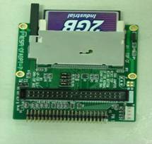
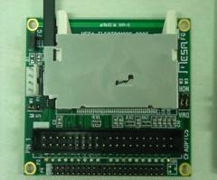
IDE TO CF Adapters
|
Adapter Supports DMA and PIO CF Cards
|
| These two IDE to CF adapter from MESA Electronics supports UDMA |
| |
|
|
| |
Adapter Supports PIO Only
|
| |
|
|
| |
Conclusion
|
| PIO supported IDE to CF adapters will support PIO CF cards and UDMA CF cards in PIO mode. UDMA supported IDE to CF adapters will support
PIO and UDMA CF cards. Making CF (through IDE interface) to work in UDMA mode in Windows CE 5.0 and Windows CE 6.0 was simple, proper IDE
to CF adapter and CF cards have to be choose. |
| |
|
|


 Mr. Thomas Yoon
 +82-10-5380-0313