| |
Introduction
|
Being a part of Windows CE driver development team, I had seen many of the queries in the newsgroups about drawing text or drawing any bitmap over the camera video stream output render.
I can think of two possible solutions for it.
One of the methods using the DirectDraw APIs you can get the surface which is above the DirectShow video renderer surface.
And the other method is using Grabber filter you can grab the frames before renderer and drawing the text over it.
I am not going to discuss much about the second method since the sample code for implementing is already available in the following PRIVATE source path of the WinCE 6.0 installation.
WINCE600\PRIVATE\TEST\MULTIMEDIA\DIRECTX\DSHOW\CAMERA
Before going into detail of this first method, just take a look at definition for DirectDraw.
|
What is DirectDraw?
|
The DirectDraw API provides support for hardware-accelerated 2-D graphics. It offers fast access to display hardware while retaining compatibility with the Windows graphics device interface (GDI). DirectDraw is a specialized memory manager for both system and display device memory and uses hardware acceleration where available. With DirectDraw, you can allocate and manipulate both system and graphics memory, including transfers between the two.
DirectDraw for Windows Embedded CE is adapted from DirectDraw for Windows-based desktop operating systems. Some capabilities from the desktop version have been extended and others have been curtailed to better suit embedded devices.
Check out the following MSDN link here to know more about the features supported by DDraw for WinCE.
In this article I am going to focus more on the sample application which will utilize the two hardware overlay layers of the application processor. |
| |
Hardware Layers in Application Processor
|
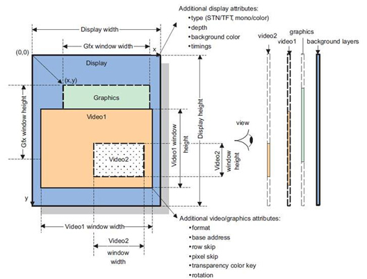
Today in most of the embedded application processor supports display controller with multi layers for giving rich user interface.
Here for reference I am showing how the display controller of OMAP35x manages the different hardware layers. |
| |
|
|
| |
So in order to utilize these different hardware layers effectively in the application, then display driver of the corresponding Window CE BSP should be a DDraw enabled driver.
So with the help of DDraw APIs we can effectively use this hardware layers stack. |
 |
Utilization of the Hardware Layers
|
In this post I am going to show the example of using the two hardware layers. My sample application is going to do two functionalities.
Prerequisites for testing this sample application:
Device should have DShow camera driver
Device should support DDraw supported Display driver.
Without the above mentioned prerequisites this application will fail to run on the devices. |
| |
This sample demo application will do the following functions when it is executed.
Using DShow it will build the filter graph and starts streaming the data from the underlying camera driver.
Using DDraw APIs it will query the surface over the camera rendering and will draw the text over it.
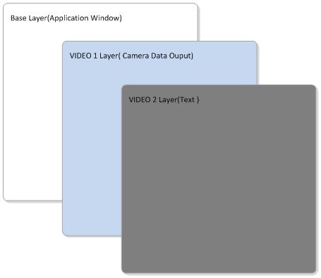
Following is the image which shows the layer management of the sample application. |
| |
 |
| |
The base layer will be used by the WinCE GWES (i.e.) functions like creating Windows drawing the controls over the windows are rendered on the Base layer of the hardware.
Using DirectShow I have built a filter graph to render the camera output on the window of the application. DirectShow supports two types of Renderers
GDI Renderer
DDraw Renderer
|
| |
GDI Renderer:
If you use the GDI renderer for rendering the output then WinCE will be rendering the camera output on the Base layer where your application window will also be residing, so it is a kind of software rendering. In this case you will not be using the hardware layers effectively and in turn will reduce the performance of the output. |
| |
DDraw Renderer:
When you select the DDraw renderer for your filter graph then the DDraw renderer will automatically query the available Overlay surface of the hardware (In this case VIDEO1 Hardware Layer) using the DDraw objects for rendering the output.
Since it is using the hardware layer, you will be getting the good performance when compared to GDI renderer. |
| |
IAMVideoRendererMode::SetMode(DWORD dwMode)
Where dwMode - AM_VIDEO_RENDERER_MODE_DDRAW (or)
AM_VIDEO_RENDERER_MODE_GDI |
|
| |
Using DirectDraw APIs we are creating a surface (In this case VIDEO2 Hardware Layer) to draw the text over the already rendered camera output (VIDEO1 Layer).
DirectShow Camera application development in Windows CE is out of scope of this article, so I am not going to explain about that part.
|
| I had taken the Mosquito application example in the PUBLIC (WINCE600\PUBLIC\DIRECTX\SDK\SAMPLES\DDRAW\SRC\MOSQUITO) directory as the base for my sample application and customized it. |
| |
DDraw Surface Creation:
|
| DDraw APIs are based on the flexible COM interface. IDirectDraw interface is the one which applications will use to create the main DirectDraw object. For creating the IDirectDraw interface object we need to call the following function, |
| |
// Create the main DirectDraw object
LPDIRECTDRAW g_pDD = NULL;
hRet = DirectDrawCreate(NULL, &g_pDD, NULL); |
|
| |
| Once the IDirectDrawobject is created, and then set the behavior of your DirectDraw object using DirectDraw::SetCooperativeLevel function call to NORMAL mode or exclusive FULLSCREEN mode. Currently in the sample application NORMAL_MODE is selected. |
| |
| hRet = g_pDD->SetCooperativeLevel(hWnd, DDSCL_NORMAL); |
|
| |
| Now the DirectDraw is initialized and we are going to create a surface so that we can start doing our actions like drawing the text etc., on the surface. First we will create the Primary surface using the IDirectDraw::CreateSurface call. Primary surface represents what is seen by the user at the moment. |
| |
ddcaps.dwSize = sizeof(ddcaps);
ddsd.ddsCaps.dwCaps = DDSCAPS_PRIMARYSURFACE;
hRet = g_pDD->CreateSurface(&ddsd, &g_pDDSPrimary, NULL); |
|
| |
|
| Once we got the primary surface we will get the Hardware capabilities exported by the DDraw display driver using the IDirectDraw::GetCaps function call. This function will fill and return the DDCAPS structure. Using this DDCAPS structure we can verify whether hardware and display driver supports the Overlay layer. |
| |
ddcaps.dwSize = sizeof(ddcaps);
hRet = g_pDD->GetCaps(&ddcaps, NULL); |
|
| |
| If the hardware supports the overlay layer then we can create the overlay surface with one back buffer, so that we can do the operations in the background buffer which is not be visible to the user. Once we are done with our drawing in the back buffer we can flip it to the primary surface. With this implementation of two buffers we can avoid the tear down effect on the screen. DDSCAPS_OVERLAY flag indicates to create an overlay Surface. DDSCAPS_FLIP indicates that the surface is part of surface flipping chain. |
| |
ddsd.ddsCaps.dwCaps = DDSCAPS_OVERLAY | DDSCAPS_FLIP;
ddsd.dwFlags = DDSD_CAPS | DDSD_HEIGHT | DDSD_WIDTH |
DDSD_BACKBUFFERCOUNT |
DDSD_PIXELFORMAT;
ddsd.dwWidth =ScreenWidth;
ddsd.dwHeight =ScreenHeight;
ddsd.dwBackBufferCount = 1;
g_pDD->CreateSurface(&ddsd, &g_pDDSOverlay, NULL); |
|
| |
| After creating the Overlay surface we need to make it as visible to the user by mapping it to the Primary Surface which we have created earlier. Using the IDirectDrawSurface::UpdateOverlay function we can achieve this. |
| |
| hRet = g_pDDSOverlay->UpdateOverlay(&rs, g_pDDSPrimary, &rd, dwUpdateFlags, &ovfx); |
|
| |
Now we will draw the text in the created overlay surface back buffer by getting the HDC of the surface using IDirectDrawSurface::GetDC function. With the acquired HDC we can play around with all the GDI functions on the overlay surface.
Since we have created a back buffer for our Overlay surface we can draw the text on the back buffer and finally we will flip it to the primary surface by using the IDirectDrawSurface::Flip function. |
| |
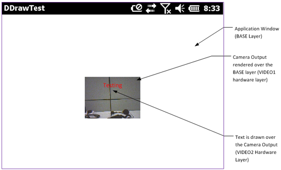
| Following is the sample screen shot of the sample application which is showing the “Testing" drawn over the camera stream output. |
|
| Click here to download the sample application source code. |
| |
 |
|
|
| |


 Mr. Thomas Yoon
 +82-10-5380-0313