Introduction
|
| The integral part of any camera is the lens and it decides the quality of the light that incidents on the image sensor and thereby decides the quality of the output image. Choosing the right lens for your application is a science, and to be precise it is more of optics. There are a number of parameters from the optical perspective to be considered for choosing the lens for meeting the application requirements. Some of these could be number of elements of lens assembly, construction of lens whether plastic or glass lens, effective focal length, magnification ratio, F/# number, Field of View, Depth of Field, Minimum object distance, IR cut filter or spectrum-specific filtering etc. These are some of the parameters that influence the selection of the lens for meeting the target application requirements. However, this article is not written from that perspective of choosing the lens from the application perspective. This article is written as guide to choose the lens that is compatible with the e-CAM50_CU5642_MOD from e-con Systems® |
| |
| This article introduces the major aspects that should be considered while choosing the lens for e-CAM50_CU5642_MOD camera module from e-con Systems®. This article does not delve too much in to optics or design of custom lens, rather focuses on the some of the aspects that should be considered while choosing a lens that works with our custom lens camera module. |
| |
 |
| |
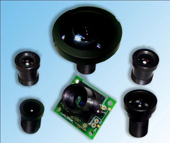
| The e-CAM50_CU5642_MOD is a camera module from e-con Systems® with a 5MP OV5642 CMOS Image sensor and an S-mount lens holder. This camera module has a parallel data interface that can be interfaced to the majority of the Application Processors such as Marvell Xscale, TI OMAP, TI SITARA, TI DaVinci, Freescale i.MX, Samsung S3C series etc. The e-CAM50_CU5642_MOD camera module is available in a tiny pluggable form factor that can be mounted on the application processor board. The e-CAM50_CU5642_MOD camera module is supported with Windows CE and Linux. e-con has an interface board that can be used to interface this e-CAM50_CU5642_MOD camera module to OMAP35x EVM board from TI and is supported by Windows CE and Linux on request. |
| |
| This e-CAM50_CU5642_MOD module is sold to customers without lens. The module has a M12 P0.5 lens holder, commonly known as S-mount camera lens holder. This allows the users of this e-CAM50_CU5642_MOD camera module to have the flexibility in selecting lens for their application. This document attempts to put forth the important parameters that should be considered while designing or choosing the lens for any application that uses this e-CAM50_CU5642_MOD camera module. |
| |
OV5642 Sensor Parameters
|
| |
| The e-CAM50_CU5642_MOD camera module uses the OV5642 - a 5MP, ¼-inch, CMOS Image sensor SOC from Omnivision Inc. As this image sensor performs the crucial function of Optical to Electrical conversion, we need to have a better understanding of this sensor, followed by the lens selection later. The web link to the OV5642 sensor is given above. The important optical details of the OV5642 sensor are given below. |
| |
| |
- Active Array size: 2592x1944 pixels
- Package area: 6945 µm x 6695 µm
- Image Area: 3673.6 µm x 2738.4 µm
- Pixel size: 1.4µm x 1.4µm (1.4 micron)
- Lens Size : 1/4 inch
- Lens Chief Ray Angle: 24° (Non-linear)
|
|
| |
| For more detailed information on rest of the parameters, please refer the OV5642 datasheet from OmniVision. |
| |
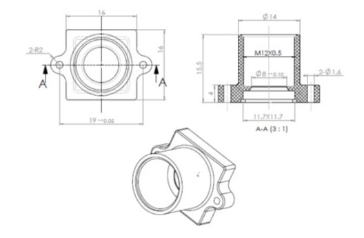
| The mechanical aspects of the S-mount lens holder of the e-CAM50_CU5642_MOD module are given below. |
| |
| |
- Lens thread: M12P 0.5
- Lens Holder height: 15.5mm
- Minimum Lens opening: 8mm dia
- Minimum distance between edge of the lens and sensor: 4mm (approx)
- Mounting holes: Two (1.6mm dia)
- Mounting stud height: 4mm
- Mounting hole distance: 19mm
|
|
| |
| For the detailed drawing and tolerances, please have a look at the drawing of the Lens Holder. |
| |
 |
| |
| The following are the major parameters to consider while choosing the lens for e-CAM50_CU5642_MOD camera module. |
| |
| |
- Sensor Size and Optical format
- Field of View
- Focal Length
- Object Dimension calculation
- Back Focal Length
- F/# & DOF
- MTF
- CRA
|
|
Sensor Size and Optical Format
|
|
| The CMOS/CCD sensors are often described by their optical format. The optical format indicates the maximum diagonal size of the imaged object on the focal plane and is historically represented in "inches". The representation is not in conventional inches, rather optical inches, where 1 optical inch is equivalent to 16mm. The Optical format is calculated by measuring the maximum diagonal size in mm and dividing by 16 and is usually denoted as a fraction. |
| |
 |
| |
| For example, for an image rectangle of width 4.51mm and height of 2.88mm, the diagonal size is about 5.35mm, dividing it by 16 gives 0.33inch or 1/3inch Optical Format. The lenses are also specified of their compatibility with respect to the CMOS/CCD sensor in terms of the optical format formed on their focus plane. For the lens, the active area is circular and lens manufacturers normally specify the diameter of the circle, known as Image Circle. |
| |
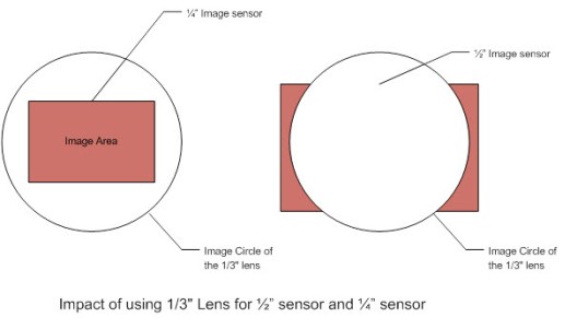
| Here is a gotcha!!! The Optical Format is a number indicating the approximate diameter of the Active Image area of the sensor. The geometry for the two sensors denoted with same Optical Format sensors need not be the same. For example, a 1/2 inchsensor can have width and height of 6.4mmx4.8mm, while another sensor of same format may have width and height of 6.61mmx4.97mm. Both the sensors are called as ½ inch sensor while the diameter varies. Even this small change in the diameter may influence the lens selection. While choosing the lens, you have to ensure that not only optical format of the lens is larger than that of the sensor, but also the Image Circle of the lens covers the entire Image Area of the sensor. Otherwise, the image formed by the lens may not fully cover the entire area of the sensor. This will result in some form of vignetting or dark on the corners of the image, as the corners are not lit. For more information on the commonly used formats and their geometrical sizes, please refer to various articles on the Internet. |
| |
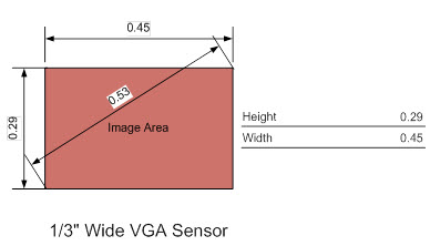
| For our OV5642 Image sensor, the width and height of 3673µm x 2738µm indicates that the sensor has ¼" Optical format. The lens chosen for this e-CAM50_CU5642_MOD module should have a minimum diameter of 4.6mm in order to avoid the dark corners on the image. This is explained below along with implication of using other optical format lenses. The figures illustrate the effects of using 1/3" Lens with ¼" sensor and ½"sensor. As it can be seen, on the ½" sensor, this 1/3" lens causes dark corners and sides. |
| |
 |
| |
| Though our Image sensor is ¼" format, the sensor is about 4.6mm in diagonal. This means that we would preferably need a Lens that is compatible with 1/3" sensor. That would allow us to have the Image circle of the lens covering our sensor area. |
| |
Field of View
|
| The Field of View (FOV) is another important parameter from the lens application perspective. The FOV requirement has to be studied from the camera application requirement and lens selection has to be made accordingly. Some of the applications might require the FOV to be wider enough to cover the larger viewing area. For example, a fish-eye lens may be a suitable lens for the surveillance application. A Fish-eye lens is characterized by wider FOV and larger Depth of Field (DOF). For a telescopic/zoom application, we might require a normal or narrow FOV. The selection of lens based on FOV/DOF is primarily application-specific and hence that is not discussed much here. However, the FOV specified by the lens for a particular sensor may not be achievable always, as their FOV measurement depends on their test conditions. Hence, you can expect a small difference in the FOV. |
| To find the right field of view required for your application, please check out our FOV Calculator. |
| |
Focal Length
|
|
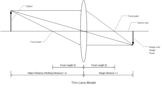
This is again a parameter to be decided based on the application requirements. However, there is an associated parameter that has to be examined thoroughly for choosing the lens for our e-CAM50_CU5642_MOD module. Before that, it is expected that you are familiar with Focal Length of an optical system and also the Effective Focal Length.
In a nutshell, the focal length is a measure of how strongly the lens converges or diverges light. This is distance between the optical center of the lens and the focal point. The focal point is the point on the optical axis, where the light rays from an object at infinite distance (these are the rays that are parallel to the optical axis) are converged. For a thin lens the optical center can be thought of as the center of the lens, however for a thick lens or a complex optical system involving multiple lenses, the optical center is somewhere inside the lens system and focal length is called as Effective Focal Length. The following diagram explains the concept of focal length using a thin-lens approximation.
|
| |
 |
| |
| From the figure, the distance between the object and the center of the lens (we are using the center of the lens, as we are modelling thin-lens) is called as w (Working distance). The distance between the lens and the image plane where image of the object is focussed is called as i. Let f be the focal distance. The focal length is calculated as follows:; |
| |
|
1/f = 1/w + 1/i
|
| |
|
The image distance where the sensor is placed from the lens is more or less fixed for each lens. So, while choosing a lens for a particular application, you have to consider the lens of appropriate focal length so that your required object distance is met with. There are lot of information available in Internet to help you in choosing the lens based on the above equation. Please note that this equation is only for a thin lens approximation. But the practical lenses are constructed with multiple glass or plastic lens elements and hence the focal length of such lens construction is specified as effective focal length.
The shorter focal lengths provide wider angle of view, whereas longer focal length provide narrow angle of view and it becomes a telephoto lens.
|
| |
Effective Focal Length
|
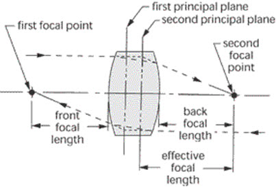
| A practical lens that we use in our applications is normally much more complex than the single thin lens as we described above. For such lens assembly (where multiple lenses are stacked together) or a thick lens, the focal length is knows as Effective Focal Length. The drawing below illustrates a EFL of a simple two element lens. |
| |
 |
| |
| From the above figure, we can assume that the thick lens is constructed using two lenses with their respective principal planes. The Effective Focal Length (EFL) or equivalent focal length is the distance from the focal points of the lens to the respective principal planes. The EFL determines the magnification of a lens and hence the image size. Because the principal planes are usually inside the lens at unknown locations, the direct measurement of the EFL is difficult. |
| |
| On a practical lens assembly where there are multiple lenses, mirror and other optical elements and their positions inside the assembly are not known, the EFL value cannot be used for checking our lens compatibility. This is due to the fact that the location of the principal plane from where the EFL is measured is not known. However as we have already selected the lens holder, we need to ensure that the lens that we chose should be able project the focussed image on the image sensor while the lens is firmly mounted on to the lens holder. If the EFL is much larger than the lens holder height, then the lens has to be placed away from the holder to project a properly focussed image. If the EFL is too small, then it may hinder the internal circular rim of the lens holder. In both cases, we cannot measure the EFL and hence we cannot decide the compatibility. So, in such cases, we use another parameter called Back Focal Length and it is explained in the next section. |
| |
Object Dimension Calculation
|
| The focal length or EFL is the value used to calculate the magnification of the system.Based on the size of the sensor (Image area), the effective focal length (EFL) of the lens and the object working distance, one can estimate the size of the object in width and height that can be projected on the sensor. There are some online calculators that can be used to estimate this. |
| |
Back Focal Length and Flange Focal Length
|
| As explained earlier, the EFL cannot be effectively or accurately used to check the compatibility of the lens with our lens holder, as the principal optical plane from where the EFL is measured is often not known. In such cases, the Back Focal Length or Flange Focal Length can be used for checking the compatibility. |
| |
 |
| |
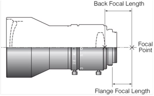
| The Back Focal Length is measured as a distance from the last optical surface of the lens assembly to the rear focal point, where the image sensor is placed. As the last optical surface (the edge of the lens that is closer to the image sensor) is often visible, this Back Focal Length parameter can be used to check the compatibility. There is also another parameter called Flange Focal Length that is measured as a distance from the flange of the lens assembly to the focal point of the lens. |
| |
| For example, in C and CS-mount lenses, the mechanical specifications related to Flange Focal Length is clearly defined. The CS mount lens has a Flange Focal Length of 12.52mm (the distance between the flange and the focal point) and for C mount lens, this is 17.52mm. So, while using the C or CS mount lens, you have to make sure that the sensor is placed exactly at the Flange Focal Length distance and the corresponding lens holder braces the flange of the lens when mounted. This will ensure that image sensor receives the focussed image. Or in other words, on a C-mount lens system, the image sensor is placed at a distance of 17.52mm from the flange of the lens. For the CS-mount lens, the sensor is placed at a distance of 12.52mm. Though all other aspects (including diameter, thread pitch etc) of the C-mount and CS-mount lenses are the same, both of them are not interchangeable, except that, any standard C-mount lens can be used on a CS-mount lens holder by using a 5mm adapter ring. However, a standard CS-mount lens cannot be compatible with a C-mount lens holder. |
| |
Using Back Focal Length
|
| Unfortunately for the S-mount lens holder, the flange distances are not defined at all. In addition, the height of the S-mount lens and the rest of the dimensions of various vendors vary a lot. In such cases, it is the Back Focal Length that plays a major role in the selection of the lens for our e-CAM50_CU5642_MOD camera module. This is because, almost all the S-mount lens manufacturers provide the Back Focal Length of their lenses and the rear optical surface of these S-mount lenses are clearly visible and can be relatively measured with respect to the edge of the lens barrel. |
| |
| The following diagrams explain the compatibility issues. In the following cross sectional diagram of the lens assembly, there are three major elements shown, the S-mount lens holder, Image sensor and the lens assembly. The lens assembly is drawn in blue with the curved surfaces denoting the optical surface of the front and rear lens elements. The image sensor is shown in brown thick line. The S-mount lens holder is shown in a thick outline in black. The protrusion of the black line inside the lens holder indicates a cross section of the circular stopper ring inside in the lens holder which would stop the lens moving down towards the sensor. For quick reference, the cross sectional drawing of the S-mount lens holder used in the e-CAM50_CU5642_MOD camera module is given below along with the dimensions. |
| |
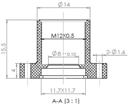 |
| |
| As it can be seen, the height of the lens holder is 15.5mm and the sensor is placed at a distance of 4mm from the annular stopper ring inside the lens holder. |
| |
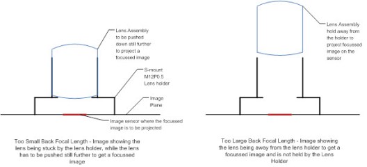 |
| |
| The first figure above illustrates the case of the lens having much shorter Back Focal Length. As the BFL is shorter, the lens has to be placed closer to the sensor to get a focussed image on the sensor. However, if the BFL is shorter than the height of the circular ring (4mm), the lens will blocked by the stopper ring and hence the image will not focussed. So, if the BFL is shorter than 4mm, then that lens will not be compatible with our lens holder. Please note that there are some tolerances of the BFL and also the height of the sensor should also be taken in to account while concluding on the lenses that have BFL very close to 4mm. |
| |
|
The second figure on the right illustrates the issue of the lens with larger BFL. If the BFL is too large, then the lens has to be placed much away from the sensor. The height of the S-mount lens holder used in the e-CAM50_CU5642_MOD sensor is 15.5mm. So, if the BFL of the lens is larger than 15.5, then the lens has to be fixed away from the lens holder of e-CAM50_CU5642_MOD to obtain a focussed image on the image sensor and hence cannot be used with our e-CAM50_CU5642_MOD camera module.
However, please note that the lenses are heavier depending on their construction and hence fitting the larger BFL lens at the edge of the lens holder of e-CAM50_CU5642_MOD may cause mechanical instability issues.
In the next part of this article, other parameters such as F/#, MTF and CRA etc shall be discussed.
|
 |
| |


 Mr. Thomas Yoon
 +82-10-5380-0313


 e-CAM50_CU5642_MOD EOL