Introduction
|
| Clearing Radiated emissions is one of the critical steps in getting FCC compliance for your Product. To get compliance, proper steps need to be taken right from the design stage. After design, a successful pre-compliance test gives you the confidence to take your Product to the Compliance Lab. |
|
Basic Concepts
|
| |
| Currents on conductors can be split into two types: differential mode currents and common mode currents. Differential mode currents and their associated radiation are caused by digital signals (and their harmonics) traveling through circuit loops. Smaller the loop, lower is the unwanted radiation. This is achieved by proper placement to ensure trace lengths are as small as possible, slowing down fast edges where possible, ensuring smallest return path by using a multi-layer board and Power/GND planes, etc. A careful and proper PCB design can reduce many of the possible emissions caused by differential mode current. |
|
| Common mode currents are more difficult to predict. Unbalanced geometries and finite impedance in the grounding system results in common mode current. The radiation from common mode current may be quite large compared to those generated from differential mode current, hence CM emissions tends to be more of an issue. |
|
Our Practical Experience - Product based on eSOM3730
|
| |
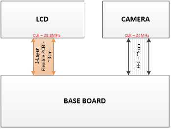
A Product based on e-con Systems DM3730 SOM, eSOM3730 was experencing the following conditions
a. Common-mode currents induced on cables attached to PCBs
b. LCD cables, connections between multiple boards
it ran into issues during pre-compliance testing.
Emissions were above limits at the harmonics of the LCD and Camera clock. During trouble shooting, the cables were identified as the source of emissions by disconnecting the cables individually and checking for emissions and also by using near field probes. |
|
 |
| Clearing Radiated Emissions |
|
| The impedance mismatch at the cables resulted in radiated emissions exceeding the permissible limits of FCC Class B. Adding an additional ground layer by making the LCD connection as a Multi-layer flexible PCB was explored, but was rejected as there were possible supply issues from the vendor. As the product design was finalized with the Camera as an external board, other means were explored to bring down emissions below permissible limits. |
|
| One of the steps taken was to slow down the edge of the display and camera signals. The aim was to reduce the higher harmonic energy in these lines. Multiple simulations were done to narrow down the best possible options. |
|
| Insertion loss varies with frequency. It is determined by the electrical configuration and source/load impedances. Different electrical configurations are available which includes the common types listed below. |
| |
| |
- C Filter - It shunts high frequency noise to ground and is suitable for use with a high impedance source and load.
- LC Filter - This is a feedthrough filter with an inductive element in combination with a capacitor. It is commonly used in a circuit with a low impedance source and a high impedance load (or vice versa)
- PI Filter - This is a feedthrough filter with 2 capacitors and an inductive element between them
|
|
| |
Examples of Simulation results
|
|
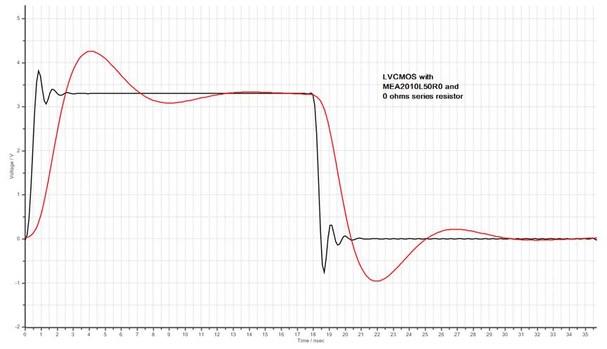
| Simulation for a 28MHz clock, LC Filter - MEA2010L50R0 Manufacturer - TDK |
|
 |
| |
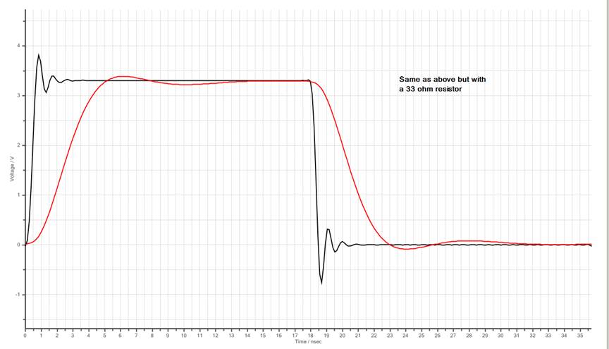
| Simulation for a 28MHz clock, LC Filter - MEA2010L50R0 Manufacturer - TDK, Series resistor |
|
 |
| |
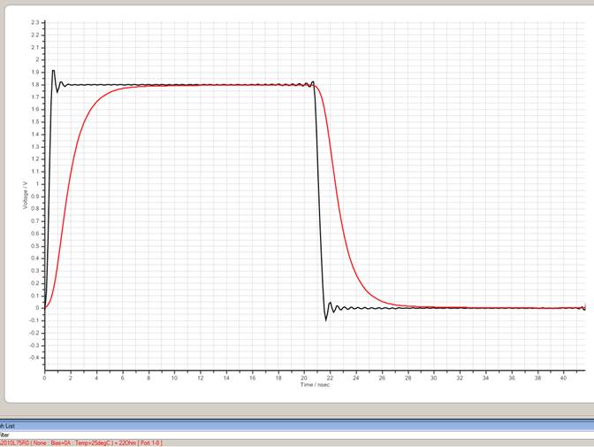
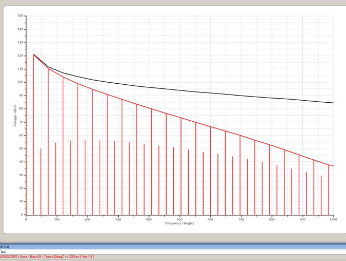
| Simulation for a 28MHz clock, LC Filter - MEA2010L75R0, 22Ω Series resistor |
|
 |
| |
 |
| |
| These filters were added in the PCB and the values modified to get optimum waveforms. Radiated emission tests were then conducted and the emissions were found to be within the Class B limits for both FCC and CISPR standards. |
|
|
Conclusion
|
| |
| It is essential that the signal travel through same impedence path. If not, required steps need to be taken to match impedence to avoid reflections and thus remove emissions. |
|
|


 Mr. Thomas Yoon
 +82-10-5380-0313