

Ethernet cameras, renowned for their efficient data transfer, integrated system functionalities, high bandwidth capabilities and a reliable connectivity, hold pivotal roles across various domains like surveillance, industrial automation, medical, and retail sectors. These cameras rely on precise timing and synchronization to capture and transmit data accurately. This is where the Precision Time Protocol (PTP) comes into play, providing a solution for achieving synchronization with sub-microsecond accuracy.
This blog explores how PTP synchronization works, the challenges it addresses, and its various modes in Ethernet cameras, highlighting the significant benefits it offers, including frame alignment, multi-camera coordination, real-time control, reduced jitter and latency, and improved data integrity.
What is PTP?
Precision Time Protocol is an Ethernet or IP-based protocol utilized for synchronizing time clocks among a group of IP connected devices. Its primary purpose is to achieve exceptionally accurate time synchronization, often reaching sub-microsecond levels of precision. This level of precision is particularly valuable in applications where precise timing and coordination among networked devices are essential. PTP’s specifications are outlined in the IEEE 1588-2008 standards, commonly known as 1588v2.
In understanding how PTP works and achieves this precision, let’s explore its operational details.
How PTP Works?
PTP operates on a master-slave architecture, which involves designating a single master device on the network as the reference clock. All other devices in the network act as slaves and synchronize their clocks to match the master’s time. This synchronization process is facilitated through a series of messages exchanged between the master and slave devices.
The key components of the PTP synchronization process are shown below.
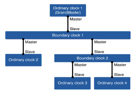 Figure 1: Key Components of PTP Synchronization
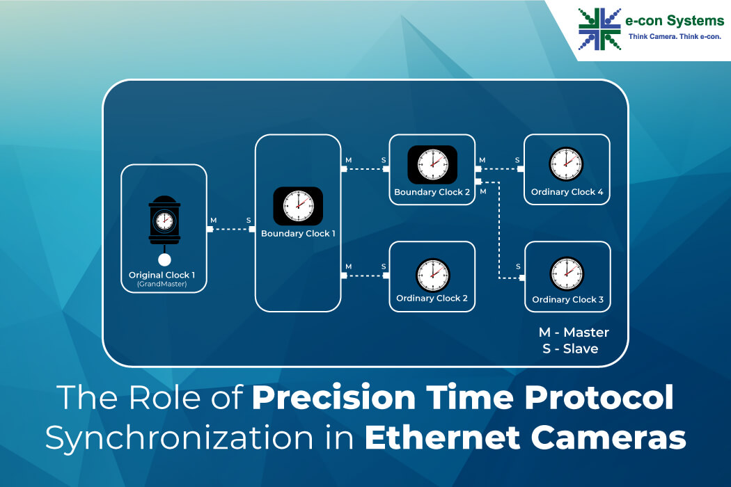
Key Components of PTP Synchronization
Grandmaster Clock: The Grandmaster Clock serves as the principal time source, often receiving highly accurate time information from sources like Global Positioning System (GPS) or atomic clocks. The Grandmaster Clock establishes the ultimate reference time for the entire PTP network.
Boundary Clocks (Masters): Boundary Clocks, also known as Masters, are intermediate devices within the PTP network. These clocks have multiple network ports, allowing them to act as clock sources for other devices. They serve as intermediaries between the Grandmaster Clock and ordinary clocks (end-user devices).
Ordinary Clocks (Members): Ordinary Clocks represent the end-user devices within the PTP network. These devices synchronize their clocks to the time provided by the Boundary Clocks or the Grandmaster Clock. Ordinary Clocks ensure that all devices in the network maintain consistent and highly accurate time.
PTP Synchronization Process
Let us now discuss how the PTP synchronization process works.
The PTP network comprises one or more communication devices, with a single network connection provided by a Grandmaster Clock device.
The simplified illustration of this process is shown below.
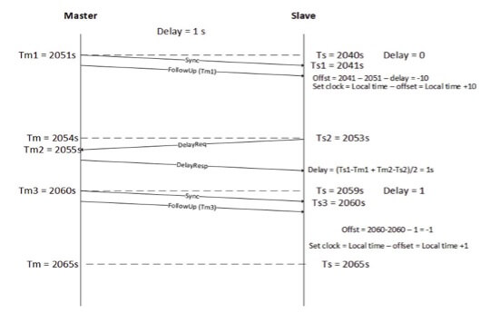 Figure 2: PTP Messages and Timestamp Exchange
The Grandmaster Clock generates an accurate time signal. This accurate time signal is transmitted over the Ethernet network in the form of PTP messages. These messages contain the time value of the Grandmaster Clock. The messages are received by the slave devices in the network, which can include both Boundary Clocks and Ordinary Clocks.
As the PTP messages propagate through the network, each device timestamps the message when it receives it. By comparing the timestamped time in the PTP message with its own local clock time, each device calculates the clock offset and delay incurred by the message as it traverses the network. Using this offset and delay information, the slave devices adjust their internal clocks to align with the time of the Grandmaster Clock. This adjustment occurs gradually to ensure a smooth transition.
The process of message exchange, timestamping, and clock adjustment is iterative and continuous, ensuring that all devices in the network remain synchronized with sub-microsecond precision.
Challenges addressed by PTP Synchronization
As described earlier, PTP synchronization provides solutions to several factors that can lead to timing inconsistencies in Ethernet network systems, including:
Time Mismatch: Devices on a network inherently have different internal clocks, leading to time mismatches.
Hardware’s Nature: Variations in hardware components can cause timing inconsistencies.
Power Fluctuations: Power interruptions and fluctuations can affect the accuracy of device clocks.
CPU Load: Processing load on devices can impact their clock accuracy.
Interrupt Latency: The time it takes for devices to respond to external events can introduce timing errors.
PTP Synchronization Modes for Ethernet Cameras
When it comes to Ethernet cameras, PTP synchronization can be implemented in two primary modes:
Master-Slave Synchronization: In this mode, one Ethernet camera is designated as the master clock, while the other cameras act as slaves. The master clock sends its precise clock signal to the slave cameras, which then adjust their internal clocks to synchronize with the master. This mode is particularly useful when one camera needs to serve as a reference for others.
Auto-Synchronization: In auto-synchronization mode, the Ethernet cameras negotiate among themselves to determine which camera will function as the master clock. This negotiation process involves the cameras exchanging clock signals and comparing their results to identify the most accurate clock source. Once the master is selected, all cameras synchronize their clocks to match the chosen master. Auto-synchronization is convenient in scenarios where the selection of a single master camera can change dynamically.
Benefits of PTP Time Synchronization in Ethernet Cameras
The advantages of implementing PTP time synchronization in Ethernet cameras are numerous and extend to various applications:
- Frame Alignment
PTP ensures that frames captured by different Ethernet cameras are precisely synchronized. This precise synchronization allows for seamless alignment and coordination in applications like video streaming and industrial automation. When events need to be reconstructed or analyzed in real time, frame alignment is crucial to maintain data integrity.
- Multi-Camera Coordination
In setups involving multiple Ethernet cameras, PTP guarantees that images and videos are accurately timestamped. This precise timing enables synchronization and correlation of events across cameras, a vital requirement for applications such as 3D reconstruction and motion analysis. Multiple cameras can work together seamlessly, capturing different perspectives of the same scene with perfect synchronization.
- Real-Time Control and Coordination
For applications requiring real-time control and coordination across networked devices, PTP is indispensable. Robotics and automation systems, for example, rely on distributed systems operating on the same time scale to ensure smooth, synchronized operation. PTP enables these systems to communicate and respond in real time, enhancing their precision and reliability.
- Reduced Jitter and Latency
PTP minimizes clock drift and network-induced jitter, resulting in smoother and more stable data transmission. This is crucial for real-time applications where even slight delays or inconsistencies can lead to performance issues.
- Improved Data Integrity
Ethernet cameras that rely on timestamped data, PTP ensures that the data is accurately timestamped, facilitating accurate analysis, correlation of events, and historical record-keeping.
Final Thoughts
PTP synchronization is a fundamental aspect of Ethernet camera technology that empowers these devices to deliver sub-microsecond accuracy in timing and synchronization. Its master-slave architecture and auto-synchronization modes ensure that Ethernet cameras can work together seamlessly, yielding benefits such as frame alignment, multi-camera coordination, and real-time control. As technology advances, PTP will continue to play a pivotal role in enabling Ethernet cameras to meet the stringent demands of various industries and applications such as Autonomous Mobile Robots, Smart farming, Smart traffic, Telepresence robots, Patient care, and Autonomous shopping.
PTP Synchronized Ethernet cameras offered by e-con Systems
With over 20 years of expertise, e-con Systems specializes in designing, developing, and manufacturing advanced GigE cameras tailored for various applications:
RouteCAM_CU86 – This 4K HDR GigE camera, featuring the Sony® IMX678 sensor and a high-performance in-built ISP, adapts well to varying lighting conditions.
Learn more about RouteCAM_CU86.
RouteCAM_CU25 – This outdoor-ready global shutter GigE camera excels in delivering accurate and fast capture of moving scenes at high frame rate, making it ideal for applications like smart traffic, road safety and law enforcement, and forklift safety.
Learn more about RouteCAM_CU25.
RouteCAM_CU22_IP67 – This rugged IP67-rated HDR Power-over-Ethernet (PoE) camera with IEEE 802.3af compliance is designed for demanding environments. Based on the Sony STARVIS IMX662 1/2.8″ CMOS image sensor, it excels in challenging conditions while maintaining exceptional image clarity.
Read more about RouteCAM_CU22_IP67
RouteCAM_CU20 – This 2MP HDR GigE camera (also IEEE 802.3af compliant), featuring the Sony STARVIS IMX462 sensor, delivers exceptional image quality. Its GigE interface allows seamless video data transfer over cable lengths of up to 100 meters. As an ONVIF-supported camera, it ensures reliable image and control data transmission over a wired LAN network.
These GigE cameras integrate seamlessly with our cutting-edge cloud-based device management platform, CloVis Central™, providing comprehensive remote management of all on-field device operations. This integration facilitates quicker time to market, cost reductions, and improved application success rates. Additionally, these Ethernet camera meets industrial-grade standards and feature PTP synchronization support. This GigE camera’s built-in ISP offers imaging controls – ensuring exceptional image quality. These GigE series cameras are highly customizable, including sensor, form factor, optics, etc.
If you require assistance with integrating this GigE camera into your embedded system, please contact us at camerasolutions@e-consystems.com.
To explore our complete camera portfolio, visit our Camera Selector.

Prabu is the Chief Technology Officer and Head of Camera Products at e-con Systems, and comes with a rich experience of more than 15 years in the embedded vision space. He brings to the table a deep knowledge in USB cameras, embedded vision cameras, vision algorithms and FPGAs. He has built 50+ camera solutions spanning various domains such as medical, industrial, agriculture, retail, biometrics, and more. He also comes with expertise in device driver development and BSP development. Currently, Prabu’s focus is to build smart camera solutions that power new age AI based applications.