

Many imaging applications commonly require the image sensor to capture an image only after a triggering action has taken place. This triggering action can be the passing of an object on a conveyor belt, the flash of a strobe light, or the press of a button.
See3CAMs (USB 3.0 Cameras) from e-con Systems™ offers the ability to synchronize the start of the image sensor’s exposure with this external triggering action. The triggering options can be broadly classified into Hardware Trigger and Software Trigger.
- Hardware Trigger
Hardware trigger as the name suggests involves triggering the See3CAM through hardware with the help of an external trigger pulse. The trigger input can go to various parts of the camera depending on the type of trigger supported in the camera. For See3CAMs in general, this trigger can either go to the Image Sensor, or the Image Signal Processor or the GPIO available in the camera.
In this type, the trigger initiates either the exposure or frame acquisition (readout) of the Image Sensor directly. The sensor will be exposed to the exposure time that is programmed into the camera. After exposure, the data is read out.
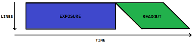
In a Global Shutter Image Sensor, all pixel rows are exposed in parallel that is, all pixels start exposing (integrating charge) simultaneously and stop exposing simultaneously. When exposure stops, the per-pixel integrated charges are digitized, transferred to memory and read out of the sensor row-by-row.
See3CAMs having Global Shutter type Sensors, can be triggered in two different modes:
- Pulsed Trigger Mode.
- Continuous Trigger Mode
PULSED TRIGGER MODE (See3CAM_10CUG, See3CAM_11CUG, See3CAM_12CUNIR and Tara)
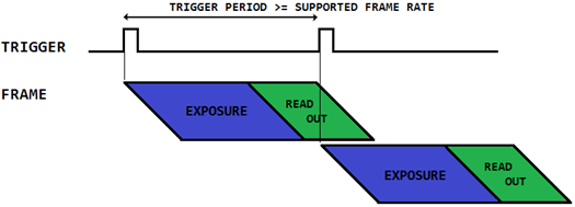
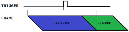
In Pulsed Trigger Mode, the exposure will start on arrival of a trigger pulse. The duration of the exposure will be as programmed in the sensor. After the completion of exposure, the frame readout will start and during the readout the sensor will not do any parallel process of exposure for next frame. After the readout, the user can send another trigger pulse to start another sequence. The entire process is sequential. Any trigger pulses before completion of a read out phase is ignored.
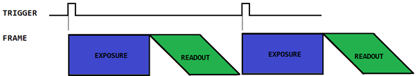
NOTE: The pictorial representation of trigger, frame exposure and readout above and in every other part of this blog is not drawn to scale and hence cannot be considered accurate. Please refer product specific documentation for complete information.
CONTINUOUS TRIGGER MODE (See3CAM_10CUG, See3CAM_11CUG, and See3CAM_12CUNIR)
In Continuous Trigger Mode, during the ON time of the Trigger pulse, the sensor will continue to output images continuously. The exposure value is programmed in the sensor. In this mode, exposure of the next frame can happen during the readout of previous frame simultaneously. Because of this simultaneous exposure, the frame rate in this mode is generally higher when compared with the pulsed trigger mode.
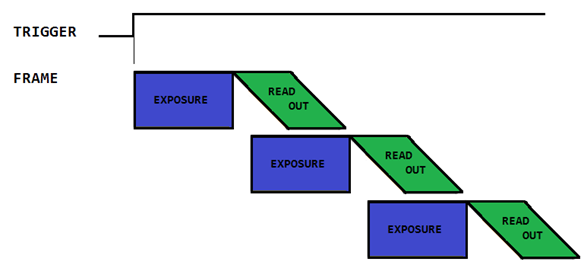
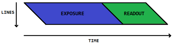
In a Rolling Shutter Image Sensor, the pixel rows are exposed sequentially one after another. After exposure of each row, the per-pixel integrated charges are digitized, and read out of the sensor row by row.
See3CAMs having Rolling Shutter type Sensors, can be triggered in three different modes:
- Fixed Exposure Mode
- Variable Exposure Mode
- Bulb Exposure Mode
FIXED EXPOSURE MODE (See3CAM_CU135, See3CAM_130)
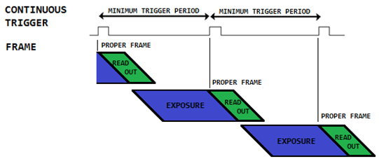
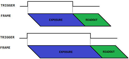
In Fixed Exposure mode, the exposure value is restricted to be set according to the supported frame rate in the camera. The rising edge of the trigger pulse is used to start the read out of an exposed frame. The Exposure time and the trigger duration should be fixed at a value equal to frame time (1/frame rate).
If the Exposure time is not equal to the frame time, then it can cause uneven exposure. For example, in a 5 fps configuration, the trigger pulse duration and exposure time has to be 200 milli sec (1/5 sec).
Exposure Time = Frame Time

Exposure Time < Frame Time
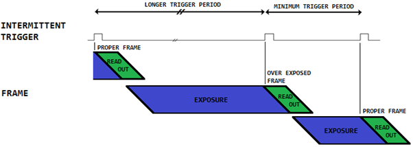
The period between trigger pulses must also be equal to the frame time. If the period goes below the programmed frame rate (minimum trigger period), the corresponding trigger pulse is ignored and if it is beyond the programmed frame rate, it results in over exposed frame.
This can happen during intermittent trigger operation, when the Trigger input is low for a long time, the first trigger pulse will result in an over exposed frame.
VARIABLE EXPOSURE MODE (See3CAM_CU20)
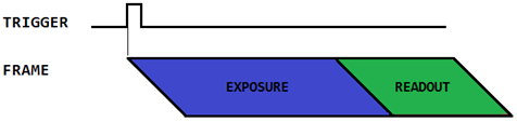
In Variable Exposure mode of trigger, there is no restriction on the exposure time with respect to the supported frame rate in the camera. The trigger pulse initiates the start of exposure and after the programmed exposure time, read out happens. Any trigger pulse before readout of first line is ignored. Increasing the trigger period doesn’t have any effect on the exposure.
BULB EXPOSURE MODE (See3CAM_CU51 (MT9P031))
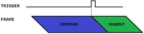
Bulb exposure mode is a special type of trigger mode which enables the user to control the exposure through the trigger rather than programming it in the sensor. The ON time of the trigger pulse decides the exposure time. When the trigger pulse is OFF, the read out starts and any trigger pulse before readout will cause corruption.
Triggering the Image Signal Processor
In this type, the trigger will not be physically connected to the Image sensor. The trigger is connected to the ISP instead and the ISP is responsible for triggering the sensor. This mode enables flexibility in the trigger duration and the exposure time unlike in sensor based triggers.
The limitation with the ISP trigger is the level of synchronization which is not very accurate as in sensor trigger. Also the ISP takes about 5 to 6 frames in order to synchronize the frames with external trigger and hence the trigger pulse has to be continuous.
There are three sync modes available through ISP trigger:
- Sync to start of frame
- Sync to start of exposure
- Sync to center of exposure
As the name suggests, this mode sync the start of frame with the rising edge of the trigger pulse.
In this mode, the start of exposure of the image is synced with the rising edge of the trigger pulse.
The below represent for an exposure time of 62.5 ms. We can see that the rising edge of the trigger pulse precedes the data by 62.5 ms, which is the start of exposure of the first pixel in the sensor array.
In this mode, the trigger is synced with the center of exposure, that is, the rising edge of the trigger is at the center between the exposure of the first pixel and readout of the last pixel.
NOTE: The support for this type of trigger is not available in the See3CAMs by default. This can be supported in See3CAM_CU130, See3CAM_CU135, See3CAM_130, See3CAM_CU30 and See3CAM_30 on request.
In this mode, the trigger goes to the USB controller. The USB controller can either grab a current frame (available by default) or control the start and stop of exposure of the Image sensor through I2C. No limitation on the exposure duration or the trigger duration in this mode.
NOTE: The GPIO trigger controlling the exposure of the image sensor is not supported by default but can be provided on request.
Trigger is sent from the application through USB protocol as extension command. The trigger goes to the USB controller, which in turn captures the current image (available by default) or controls the start and stop of exposure of the Image sensor through I2C. No physical hardware connection required except for the USB cable.
NOTE: The Software trigger controlling the exposure of the image sensor is not supported by default but can be provided on request.
In the above methods of triggering, the level of synchronization (that is the consistency of delay between the trigger pulse and the start of exposure) decreases as below,
Sensor Trigger > ISP Trigger > GPIO Trigger > Software Trigger
The increasing ease of use of the trigger will be in the opposite as above.
2 comments
Can you give a little bit more details about this?
How do we actually trigger cameras through software? Is there an api for this? For linux would we use v4l2 to do this and take to shots nearly at the same time? Or is there an explicit trigger command through usb?
Software trigger isn’t available by default in our cameras. Based on your requirement, we can provide support to trigger through an Extension USB command. For more information, please contact sales@e-consystems.com