

Image processing platforms are rapidly advancing to provide reliable and cost-effective embedded vision solutions across different markets. Some of the common image processing techniques can improve the image quality by correcting illumination, rescaling the image (digital zoom), detecting edges, evaluating and ranking segmentation algorithms, etc. They do so by leveraging image enhancement, restoration, encoding, and compression. Many image sensors integrate these image processing modules on a chip circuit.
Complementary Metal Oxide Semiconductor (CMOS) is the most common type of image sensor used in today’s embedded vision applications. CMOS cameras receive light to form a pixel array. These cameras need the right optics (or lens) to be able to capture image data ready for the various types of processing mentioned before. However, picking the best-fit lens and integrating it with the camera module comes with its own set of challenges. These include determining the right FOV (field of view) for the application, choosing the right focus type (fixed focus or autofocus), fixing the working distance, etc. To make it worse, phenomena like lens vignetting and white balance issue also corrupts the image output.
What is lens vignetting?
Lens vignetting refers to the gradual reduction of an image’s brightness or saturation from the image center to the four corners/edges. Also known as lens shading, light fall-off or luminance shading, it depends on the lens aperture and several lens design parameters. This fall-off is measured in f-stops.
The aperture controls the image’s brightness by altering the overall amount of light that reaches the camera sensor through the lens. The below test image shows luminance shading from center to the four corners.

What causes lens vignetting? What are its different types?
Some of the causes of lens vignetting can be the optics itself. The phenomenon can be increased/intensified due to blockage of the light beam by using external tools like filters, filter holders and lens hoods. At times, it is also added in post-processing to draw the viewer’s eye away from the distractions in the corner and towards the center of the image.
Given below are the different types of lens vignetting:
- Light Ray roll-off
- Vignetting caused due to Chief Ray Angle (CRA)
- Mechanical vignetting
Light Ray Roll-off
There are two types of light ray roll-off vignetting – optical vignetting and natural vignetting. Optical vignetting is caused due to the reduction in effective lens opening for off-axis incident light. This results in a gradual decrease of the brightness towards the image periphery – depending on the physical dimensions of a multiple-element lens.
Natural vignetting is the decrease in Relative Luminance (RI) with respect to the field, and is governed by the ‘cosine fourth’ law of illumination fall-off. Here, the maximum brightness of the image circle produced by a lens with no vignetting is limited by the fourth power of the cosine of the CRA (Chief Ray Angle) in image space. This type of vignetting is also known as cos4θ roll-off. This is a natural phenomenon and can be addressed during post-production.
Chief Ray Angle (CRA)
CRA is one of the important parameters for the selection of lenses and sensors. It affects the image quality by creating shadows on the image edges. The actual CRA of the lens is dependent on the lens design, not the sensor – and is determined by the rays passing through the lens. The efficiency of the light incident on the CMOS or charge-coupled device (CCD) sensor is not only related to the CRA but also related to the microlens of the sensor.
You can see the vignetting effects occurred on edge pixels due to CRA in the below image.
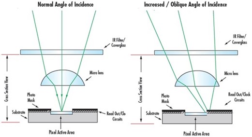
As you can see in the above illustration, all the rays are focused onto the active area of the pixel if the light is focused at normal incidence. Not all rays make it to the active pixel area at an oblique incidence.
Mechanical Vignetting
Mechanical vignetting occurs when the light beam is mechanically blocked by the lens mount, filter rings or other objects, and causes shading towards the edges of the image. It is found mainly when the image format (or circle) of the lens is too small for the sensor’s size.
What are the approaches to correct lens vignetting?
As discussed before, vignetting is an undesirable phenomenon, and it is impossible to fully prevent its occurrence. But it is necessary to use the methods for vignetting correction in embedded cameras to achieve the desired image quality. Let’s look at some of the approaches used to correct lens vignetting.
Matching CRA value of sensors with lenses
The CRA value of the lens must be less than the CRA value of the sensor’s microlens to eliminate the imaging illumination or color problems. Therefore, manufacturers must check the lens design to match their sensor layout.
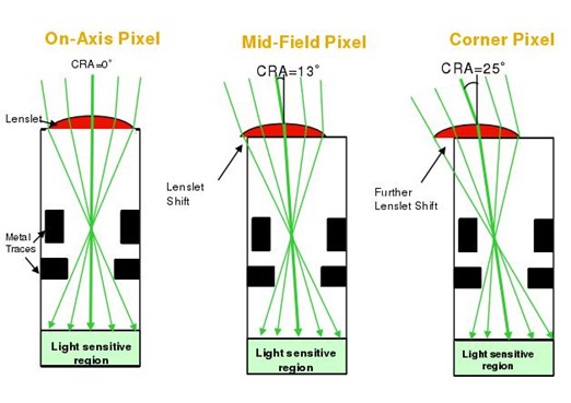
The CRA mismatch effect can be corrected by shifting the microlens on each pixel, as shown below:
Tuning the ISP
The ISP plays a major role in processing the image taken from the sensor. Each ISP has a specific method to mitigate lens shading through a series of procedures. For instance, Imatest can be performed to test the image quality. ISO 17957 was implemented in the Imatest Uniformity and Uniformity Interactive (UI) modules. When the Imatest uniformity procedure is performed, you can view the lumination non-uniformity in the plot shown below.
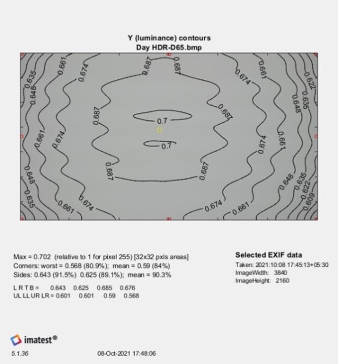
In the uniform luminance result, the side and corner regions are shown as red rectangles. A yellow circle indicates the approximate location of the maximum luminance. L R T B values are the luminance values at the left, right, top and bottom sides of the averaged image file respectively. The UL (Upper Left), LL (Lower Left), UR (Upper Right), and LR (Lower Right) values are the luminance values of the four corners. Based on the above luminance uniformity result, the specific registers in ISP can be tuned or calibrated.
Increasing the numerical f-stop number
Natural vignetting or cos4θ roll-off can be avoided if the lens is stepped down by two f-stops that increase the numerical f-stop number.
Using a longer focal length
Vignetting can also be caused in cases like lower f/#s (ratio of the focal length to the aperture size), short focal length lenses, or lenses where higher resolutions need to be achieved at a lower cost. Mechanical vignetting is the only type that can be eliminated by using a camera technique (using a longer focal length).
Ensuring flat-field correction
Flat-field correction is the most frequently used approach for vignetting correction. In this approach, the flat surface is uniformly illuminated with a uniform color. This approach is performed by following the steps given below:
- Acquire the dark field reference frame obtained with the lens cap covering the lens
- Acquire the light reference
- Calculate flat-field correction using the acquired dark field reference and light reference

Using software tools
Several software tools such as microscopy image stitching tools, CamTool, etc., are available for lens shading correction.
Using a telecentric lens
Manufacturers can design lenses to be image space telecentric to correct roll-off, as this telecentricity produces extremely uniform image plane illumination. Since all chief rays have an angle of θ with respect to the image plane, the normal cos4θ fall-off in the image plane illumination from the optical axis to the corner of the field is removed.
We hope that this blog helped clear all your doubts about lens vignetting. If you have any further queries on how you can overcome this issue in your embedded vision applications, please leave a comment.
If you’re interested in integrating embedded cameras into your products, kindly write to us at camerasolutions@e-consystems.com. You can also visit our Camera Selector to get a complete view of e-con Systems’ camera portfolio.

Prabu is the Chief Technology Officer and Head of Camera Products at e-con Systems, and comes with a rich experience of more than 15 years in the embedded vision space. He brings to the table a deep knowledge in USB cameras, embedded vision cameras, vision algorithms and FPGAs. He has built 50+ camera solutions spanning various domains such as medical, industrial, agriculture, retail, biometrics, and more. He also comes with expertise in device driver development and BSP development. Currently, Prabu’s focus is to build smart camera solutions that power new age AI based applications.