



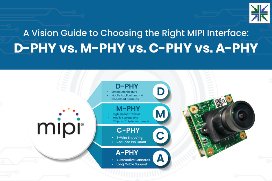
MIPI technology has evolved through multiple versions, particularly in its physical (PHY) layers. These help enable high-speed serial communication architectures that replace traditional parallel camera and display interfaces, improving bandwidth scalability, power efficiency, and EMI performance.
The MIPI physical layers: M‑PHY, C‑PHY, D‑PHY, and A‑PHY are actively used in embedded applications, including mobile robots, AMRs, and AGVs that require multi-camera solutions. Among these, A‑PHY is the latest automotive physical layer.
Since the advent of the MIPI specification, there have been many updates to all the physical layer standards. Different physical layers support specific MIPI logical-layer CSI versions, such as CSI-1, CSI-2, and CSI-3. Notably, some physical layers can coexist with other physical layers within the same processor, enabling high-performance embedded vision systems.
In this blog, you will learn about the four MIPI physical layers — D-PHY, C-PHY, M-PHY, and A-PHY — how each one meets the needs of modern embedded systems, and how they compare across key performance parameters.
What is MIPI Physical Layer?
Mobile Industry Processor Interface (MIPI) defines the physical layer for transmitting data and lane management between devices, such as automotive cameras, displays, and processors, using protocols such as CSI-2 and DSI. It ensures that signals are delivered reliably, even in environments with electrical noise — a common challenge in vision systems. Over time, MIPI has introduced multiple MIPI PHY versions, each optimized for specific applications.
- D‑PHY is the most widely adopted for camera (CSI‑2) and display (DSI) interfaces.
- C‑PHY supports camera and display using three‑wire signaling for efficiency and reduced pin count
- M‑PHY focuses on high‑speed, low‑power mobile applications.
- A‑PHY is the latest, designed for long‑reach automotive use cases with strong EMI immunity.
Overview of MIPI PHY Family
The four PHYs were introduced in the order D → M → C → A. MIPI D-PHY was introduced as the first physical-layer standard. The D-PHY, C-PHY, M-PHY, and A-PHY physical layers were subsequently released to meet the demand for higher bandwidth and greater efficiency in embedded vision applications. Each was designed to address specific limitations of D-PHY and to serve distinct application areas. All the PHY layers continue to scale for high-performance vision systems.
Let’s look at each PHY layer in sequence.
-
D-PHY
D-PHY is a short-reach, synchronous serial interface introduced more than 15 years ago that has been predominantly used in mobile applications and embedded cameras for decades. It uses differential signaling and has a high-speed (HS) mode for data transmission and a low-power mode for the control signal.
In the diagram below, the image sensor, acting as the transmitter, sends data to the processor, acting as the receiver, via the MIPI CSI-2 interface. This communication architecture is commonly used in embedded vision systems based on NVIDIA® Jetson™ camera modules.
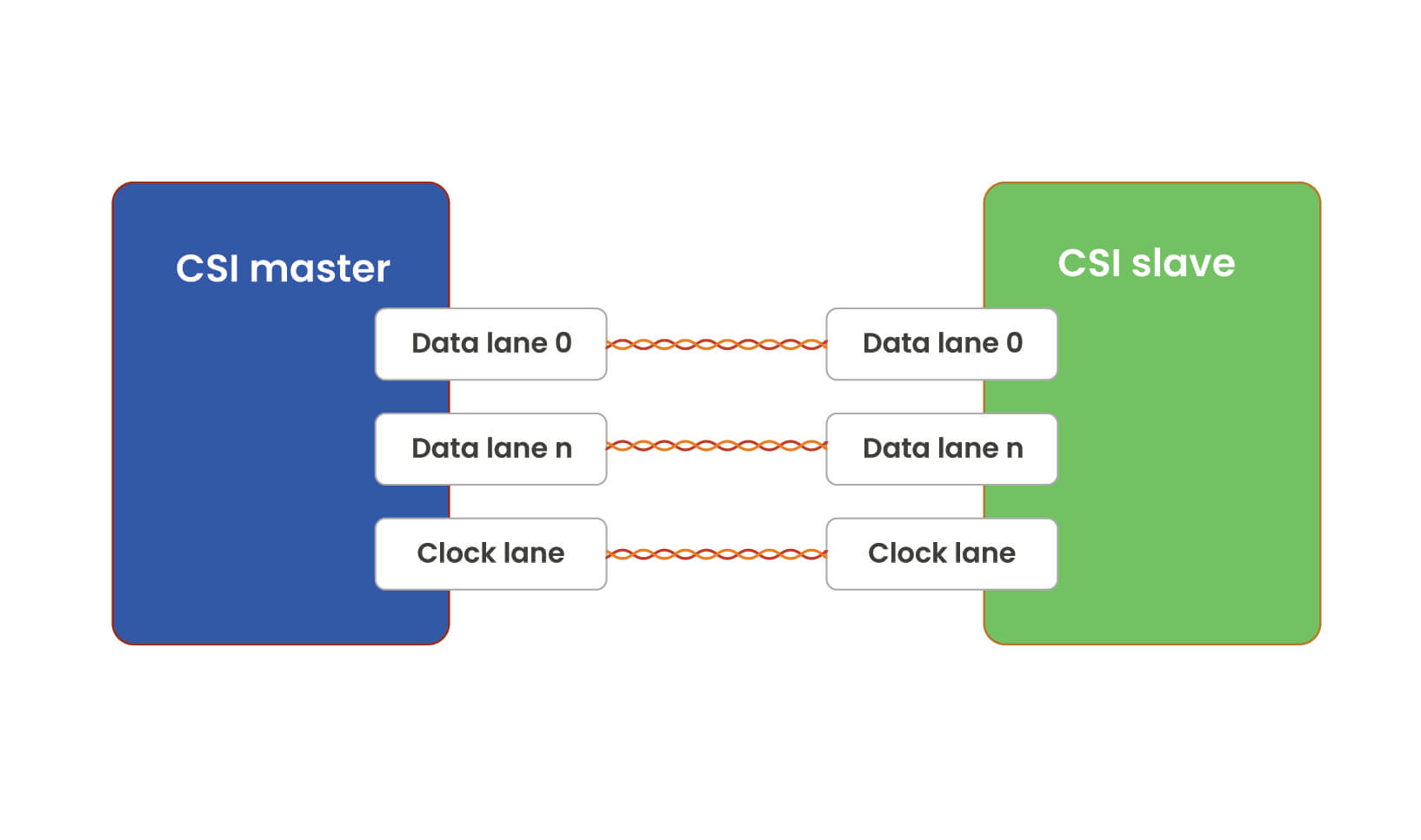 The architecture uses high-speed differential lanes consisting of:
- Data lanes for image/video transfer
- A clock lane for synchronization
It also supports the MIPI DSI interface used for displays, where the direction is reversed — the host processor transmits display data, and the display receives it.
MIPI defines that D-PHY version v3.0 supports up to 9 Gigabits per second (Gbps) per lane, or 36 Gbps (four lanes). It supports cable lengths of 10–30 cm for PCBs or short FFCs. It covers a wide range of applications, including ITS, smart surveillance and more.
Also read: What is a MIPI Camera? How does MIPI Camera Work? – e-con Systems
-
M-PHY
M-PHY was introduced in 2011 and supports both self-clocking and embedded clocking. M-PHY is primarily used in mobile storage and chip-to-chip interconnects rather than mainstream embedded camera interfaces. The figure below shows the block diagram of the M-PHY.
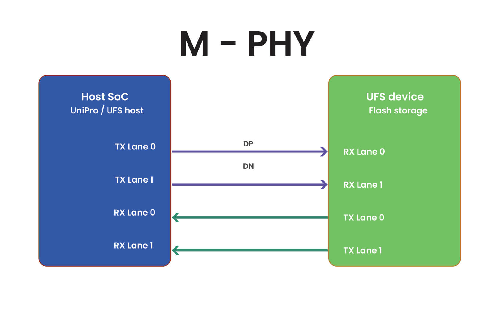 Each lane is one differential pair (DP, DN). The clock is embedded in the data stream. MIPI M-PHY uses embedded clock signaling and supports full-duplex communication, allowing simultaneous data transmission and reception between the UFS host and device through separate transmit and receive lanes. Its pin count is low, making it suitable for universal flash storage devices and chip-to-chip communication applications.
M-PHY supports PCB lengths of 10–30 cm. Because of its low-voltage-swing operation, it achieves low EMI. It includes two modes: high and low speeds, which are crucial for scenarios where power consumption can be traded off.
-
C-PHY
MIPI C-PHY was added to the MIPI PHY family in 2014 and is the serial physical layer for short-reach connections. The C-PHY uses a 3-wire group called Trios, unlike D-PHY, which uses 2 wires per lane. It lacks a separate clock.
The block diagram below illustrates how the image sensor transmits image/video data over the MIPI CSI-2 protocol to the processor using the C-PHY communication link.
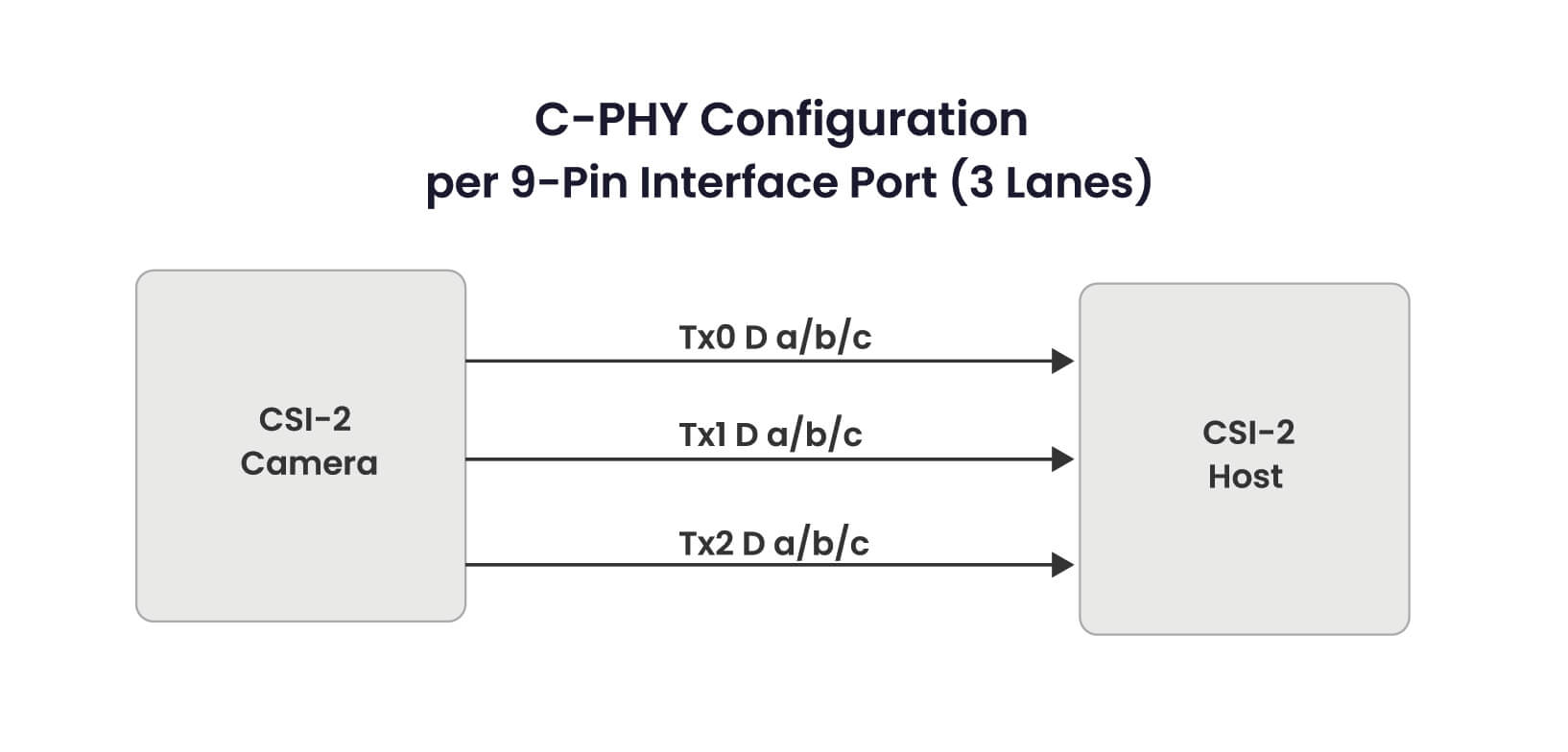 In the diagram above, the number of lanes is three (0,1,2), and the three wires (a, b, and c) in each lane carry both data and synchronization information simultaneously. Since C-PHY embeds clock information within signal transitions, it eliminates the need for a dedicated clock lane, improving bandwidth efficiency and reducing pin count in embedded cameras.
The channel can transmit 2.28 bits per three-wire lane. C-PHY uses three-wire trio signaling with encoded state transitions rather than traditional differential lane pairs. MIPI defines that C-PHY version 2.1 supports up to 7.5 Gsps per lane, or 51.4 Gbps per 3 trios, due to its new encoding technique. Due to similar electrical characteristics, C‑PHY and D‑PHY can be implemented on the same device pins. It supports lengths of 10–30 cm for PCBs or short FFCs.
-
A-PHY
A-PHY, the most recent, was released in September 2020 and is an asymmetric SerDes (Serializer-Deserializer) data link that supports long-distance communication over a single unshielded twisted pair (UTP) or STP cable up to 15m and is used in automotive cameras.
The figure below shows the block diagram of the MIPI A-PHY.
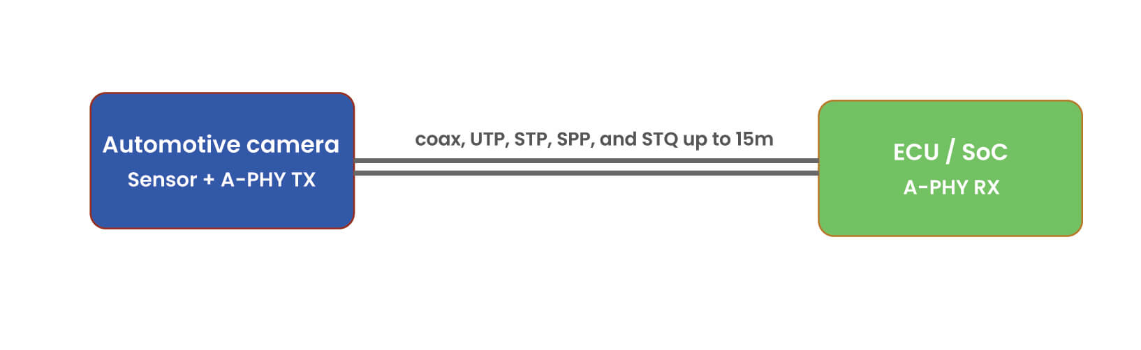 This asymmetric SerDes (Serializer-Deserializer) A-PHY interface transfers image data from the camera to the ECU in the forward link at high speed, while in the reverse link, it carries control and configuration data back to the camera at a lower speed. This transmits high-speed video, low-speed control data, and optional power delivery over a single long-distance cable.
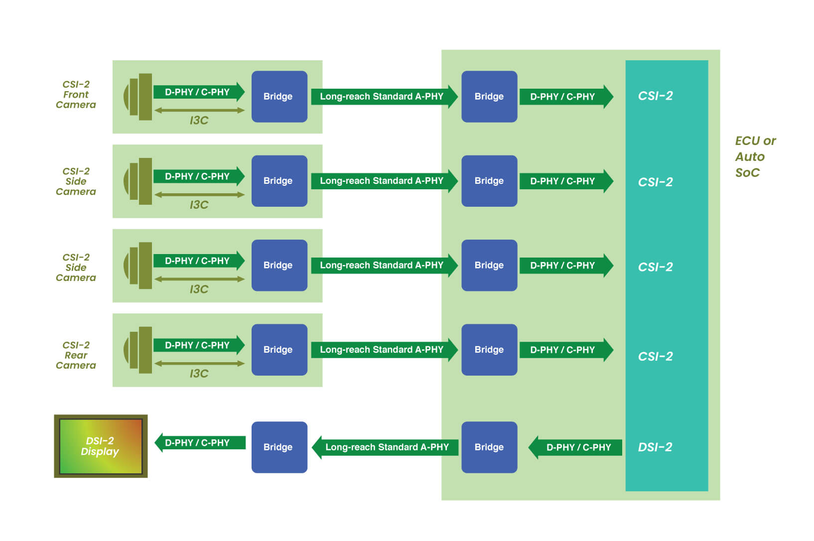
Most embedded cameras use MIPI D-PHY or C-PHY interfaces, which are designed for short-range, high-speed communication. To enable long-reach transmission, bridge chips are typically used to convert CSI-2 data into long-distance SerDes formats.
MIPI A-PHY now enables standardized long-reach connectivity between CSI-2 cameras and ECUs/SoCs.
The figure below illustrates how a CSI-2 camera with D-PHY/C-PHY interfaces communicates with a CSI-2 ECU/SoC over a long-reach MIPI A-PHY link through bridge chips. This architecture helps reuse existing camera infrastructure while simplifying system design and reducing overall cost for long-distance applications.
Alternatively, an automotive camera can integrate native A-PHY support and connect directly to the CSI-2 ECU/SoC through an A-PHY communication link, as shown in the figure below.
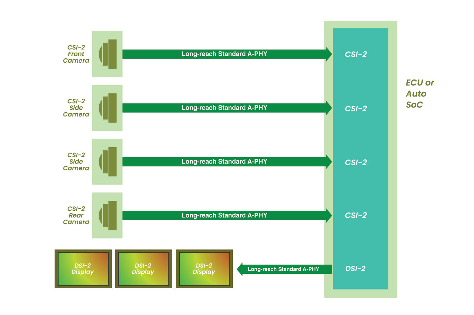 Through the direct MIPI A-PHY architecture shown in the diagram above, bridge chips between the camera module and the ECU/SoC are eliminated, simplifying the overall system design, reducing component count, lowering latency, and improving reliability — one of the key advantages of MIPI A-PHY for next-generation vision systems.
The A-PHY version 2.0 supports 16 Gigabits per second (Gbps) to 32 Gbps at a downlink data rate on a single channel. A-PHY offers two profile types, allowing performance-critical applications to select the one best suited to their needs. It is designed for strong EMI resistance, achieved through forward error correction (FEC) and shielding.
The optimized asymmetric architecture provides high-speed communication between the embedded camera and the ECU and simplifies the design compared to symmetric architectures. It supports cable lengths up to 15m.
Comparing MIPI PHY Layers: Which One Should You Use?
| Feature | D-PHY | C-PHY | A-PHY | M-PHY |
| Application Area | ADAS, surround view system, surveillance, industrial, mobility and ITS | Embedded cameras, AR, and VR | ADAS, surround view system, surveillance, industrial, mobility and ITS | Chip-to-chip communication |
| Architecture | Source-synchronous clock with separate clock and data lanes | 3-wire trio signaling with embedded clock | Long-reach asymmetric SerDes over coax, UTP, STP, SPP, and STQ | Embedded/self-clock |
| Maximum supported rate | 9 Gbps on a standard channel and a short channel (version 3.6) | (17.8) Gbps on standard channel and 24.9 Gbps on short channel effective per trio (version 3.1) | Up to 32 Gbps (version 2.0) | 46.694 Gbps per lane on mobile standard channel (version 6.0) |
| Transmission Distance | Short (<30cm, on PCB) | Medium (<30cm, inter-board) | Long (<15m, automotive cables) | Short |
Final Thoughts
Each MIPI PHY layer is designed to solve specific challenges in vision applications. To summarize, D-PHY and A-PHY are used for vision use cases, preferring D-PHY for short-range transmission and A-PHY for long-range transmission.
While A-PHY is in the early adoption phase, sensors and other ecosystem components are continuing to progress. However, existing SerDes-based long-distance camera solutions, such as FPD-Link IV and GMSL2/3 camera modules, are widely deployed across industries for long-reach applications. These ecosystems continue to evolve as advancements in sensor, lens, and camera assembly technologies unfold.
In addition, they offer seamless integration with leading processing platforms, including NVIDIA Jetson, Qualcomm processors, Texas Instruments processors, and other embedded computing platforms.
Enhance Vision Power with e-con Systems’ Automotive Cameras
Since 2003, e-con Systems has been designing, developing, and manufacturing OEM and ODM cameras for the most demanding applications worldwide. We are committed to leveraging state-of-the-art vision technologies to meet the needs of emerging high-performance vision systems.
We turn complex vision challenges into reliable, scalable solutions, delivering cameras that span interfaces including MIPI, FPD-Link IV, GMSL-3, USB and GigE. They come with IP-rated durability, high-resolution imaging, flexible deployment across popular processing platforms, and more.
Use our Camera Selector to zero in on the best-fit camera for your automotive systems.
Looking for a customized camera solution to overcome a unique vision challenge? Please reach out to our experts at camerasolutions@e-consystems.com.

Prabu is the Chief Technology Officer and Head of Camera Products at e-con Systems, and comes with a rich experience of more than 15 years in the embedded vision space. He brings to the table a deep knowledge in USB cameras, embedded vision cameras, vision algorithms and FPGAs. He has built 50+ camera solutions spanning various domains such as medical, industrial, agriculture, retail, biometrics, and more. He also comes with expertise in device driver development and BSP development. Currently, Prabu’s focus is to build smart camera solutions that power new age AI based applications.