



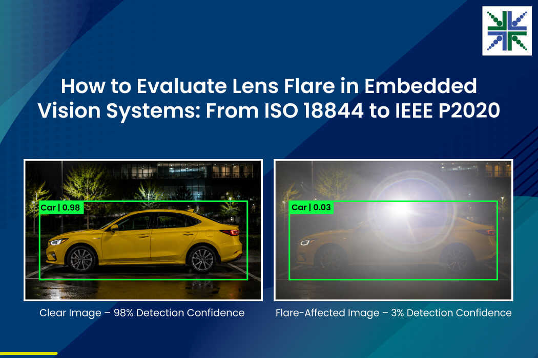
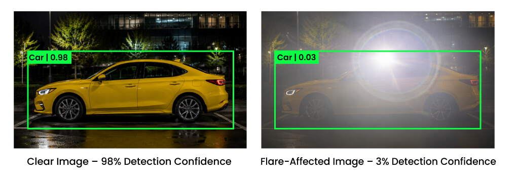
When evaluating the performance of a camera system, it is easy to assume that image artifacts stem from the digital sensor or the Image Signal Processor (ISP). However, one of the most stubborn and destructive phenomena in embedded vision is purely optical: Lens Flare.
Our previous blog explored how optical design, coatings, and mechanical controls can reduce lens flare in embedded vision systems. The next challenge is determining how much stray light remains, where it appears in the frame, and which incident angles expose the lens to flare.
A visual inspection alone can’t answer these questions. Flare evaluation needs to distinguish broad veiling glare from localized ghosting and streaks, measure their intensity, and reveal how they can affect image data used by automotive, surveillance, traffic monitoring, and ALPR systems.
In this blog, you’ll find out how e-con Systems evaluates lens flare using ISO 18844 Method C, Advanced Stray Light Analysis, and Objective Visual Analysis, as well as get more information on how we help mitigate it.
The Impact of Flare on Embedded Vision Applications
ADAS and automotive driving
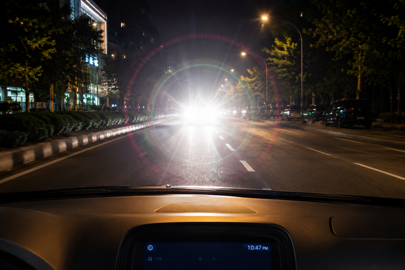
In automotive applications, cameras serve as the eyes of the entire vehicle. When optics introduce flare, those eyes struggle to see clearly. For instance, Lane-Keep Assist systems rely on detecting the high-contrast lines of painted road markings. If streaks or veiling glare obscure those regions, the vehicle may drift out of its lane.
Similarly, heavy veiling glare from a bright sunset can cover the frame in a haze, blinding object detection algorithms to incorrectly detect pedestrians or obstacles.
Surveillance and security
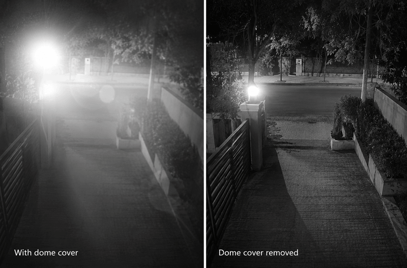
Security cameras are frequently tasked with face detection or identifying intruders in challenging lighting. If an outdoor camera lacks a protective lens hood or Dome cover, bright light striking at an extreme angle will cause veiling glare.
This glare washes out critical details in the shadows and compresses the dynamic range, resulting in failed detections precisely when they are needed most.
Traffic monitoring systems
Traffic cameras are constantly subjected to bright point-lights, from vehicle headlights to direct sunlight. When ghosting occurs, tracking algorithms can trigger false alarms, mistaking the artifacts for approaching objects. Also, streaks cause severe blooming around headlights.
If the detection algorithm cannot isolate individual vehicle lights through the bloom, it interferes with vehicle counting and speed-tracking accuracy.
 Automatic License Plate Recognition (ALPR)
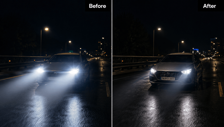
ALPR systems rely on a strict sequence of data processing. It includes identifying the vehicle, isolating the plate, and passing the text to an Optical Character Recognition (OCR) engine. Since the headlights are very bright objects, if streaks are produced from those spots, it drops the local contrast of the region.
The number plate near the headlight becomes difficult to capture with maximum contrast and clarity. As OCR engines require sharp, high-frequency transitions between characters to read accurately, flare causes the recognition process to fail.
How e-con Systems Evaluates Stray Light
To guarantee reliability in challenging environments, e-con Systems rigorously evaluates camera optics for flare vulnerabilities using a multi-tiered approach.
The ISO 18844 Method C (Veiling Glare Testing)
Veiling glare typically occurs when a bright object sits just at the edge or outside of the frame, destroying midtone definitions. We quantify this using the industry-standard ISO 18844 Flare Method C.
Setup
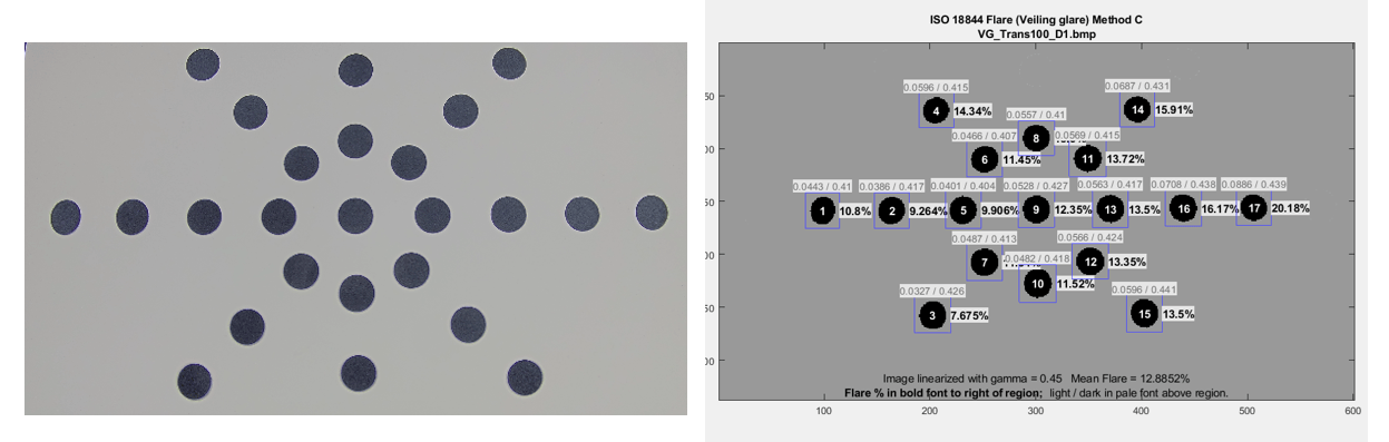
- We use a specialized transmissive chart where the majority of the surface is transparent, peppered with specific black dots designed to perfectly obstruct the backlight.
- The testing environment is kept pitch black to isolate the camera from any ambient room light.
Testing
The back illumination intensity and camera exposure are manually adjusted so that the white, transparent regions of the chart achieve a high brightness (normalized to a pixel value of roughly 225 in an 8-bit image).
Results
We analyze the pixel values of the purely dark and heavily bright regions. Under ideal conditions, the pixel values should perfectly reflect the contrast ratio of the physical chart. But veiling glare causes light to leak into the circumferences of the black dots, elevating their pixel values. We use these compromised dark regions to characterize the overall veiling glare percentage of the camera.
 |
||
| The ISO18844 chart image was captured along with Imatest results, where the veiling glare percentage is calculated by the amount of influence of the bright light near the circumference of the black dots. | ||
Advanced Stray Light Analysis
Since the ISO 18844 method has limitations, primarily its inability to map localized ghosts and streaks, we use an advanced Stray Light Analysis setup. This method masks the primary light source and mathematically characterizes all other unwanted light in the frame.
Setup
- A highly concentrated, collimated light source is aimed at the lens to deliberately trigger various flare types.
- An unsaturated image of this light source is captured first as a baseline reference frame.
Testing
The bright light is swept across the lens from both on-axis and off-axis angles, studying the optical reaction in every possible orientation. The unsaturated reference frame serves two purposes. Firstly, it allows the software to properly mask out the physical light source (excluding it from the flare math).
Secondly, it provides a peak pixel value to calculate the Point Source Rejection Ratio (PSRR), determining exactly what fraction of the light source’s original power leaked into any given stray pixel.
Results
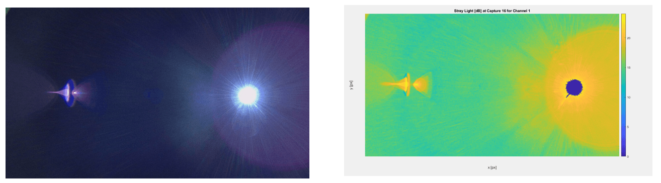
With the center source masked away, every other illuminated pixel is categorized as stray light. These linear sensor values are translated into logarithmic or decibel (dB) scales and mapped by color based on intensity. This color map clearly isolates characteristic ghosting and streaks.
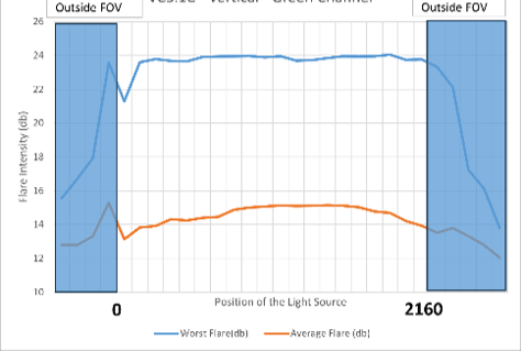
Moreover, adhering to IEEE P2020 standards, we map the average and maximum flare intensities across the entire frame. By plotting flare intensities across various orientations, we can map the exact angles where the lens is most vulnerable.
 |
||
| Image and corresponding color-mapped result generated. Similarly, the light is swept across the axis, and the color-mapped results are saved as GIFs to observe the behavior across different orientations. | ||
 |
||
| The Average and Maximum intensities of Flare observed in each frame are then plotted in compliance with the P2020 standard to observe the behavior when light is incident from on-axis and off-axis. | ||
Objective Visual Analysis
Particularly for automotive applications utilizing High Dynamic Range (HDR) sensors, it is imperative to choose optics that protect shadow details from flare degradation.
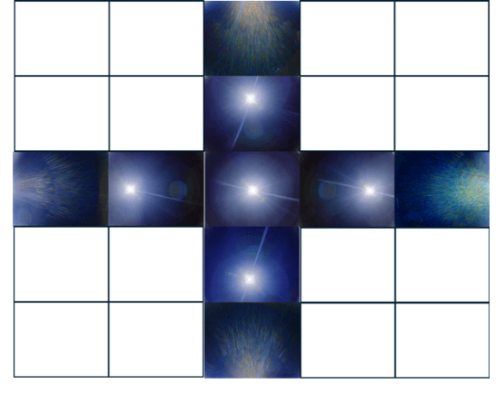
Alongside the math, we conduct rigorous visual characterizations of specific flare patterns, such as petal flare, ring flare, streaks, and ghosting.
This documents their occurrence at specific angles and intensities before a camera is ever deployed in the field.
 |
||
| For applications like automotive cameras, we characterize the flare behavior based on the orientation and angle at which the light is incident on the surface of the lens, based on whether it’s a flare/veiling glare/ghosting and understand its intensity and impact on the output frame. | ||
Mitigating the Inevitability of Lens Flares: More Best Practices
As long as a camera system consists of glass elements and operates near bright light sources, it is mathematically impossible to completely eradicate all forms of flare. By strictly controlling the variables, we can prevent stray light from destroying system performance. In our previous blog about lens flare mitigation, you learned how flare can be tested and reduced through optical design, AR coatings, blackened internal components, and mechanical shielding.
In the case of finding a characteristic flare and isolating the issue to the AR coatings, here are a few quick methods to improve the individual components and boost the overall performance of the lens.
The primary suspects when a coating-related query arises are:
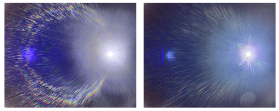
- If there is a characteristic ring emerging from a bright light source, it may be due to the reflections off the circumference of the lens component and a simple black coating on the individual lens outer circumference can help reduce this drastically.
- If the veiling glare or streaks are predominant, the surfaces where the chances of internal reflection are higher based on simulation data can be given another layer of coating or an improved material coating.
- If there is a coating for another purpose, say a hydrophobic coating or IR cut coating on the same surface as AR coating, due to air gaps between the two layers, streaks might be generated. The coating efficiency is then revisited to mitigate the flare.
 |
||
| A characteristic ring flare is observed and then mitigated by applying one of the above-mentioned improvements to the internal components based on simulation data and the observed flare. | ||
Final Thoughts
Lens flare might add cinematic warmth and make the frame aesthetic. But in the demanding landscape of embedded vision, flare is a critical vulnerability. When an autonomous vehicle navigates a dark tunnel into blinding sunlight, or when a security camera tries to capture a license plate under intense headlights, optical performance dictates system safety.
As vision systems become increasingly reliant on machine learning and computer vision algorithms, the vision must be as clear as possible for the algorithms to make a decision. Algorithmic post-processing and ISP tuning are highly powerful tools, but they can’t reconstruct data that has already been mathematically buried by veiling glare or clipped by ghosting.
e-con Systems Offers Vision Solutions With Intelligent Flare Mitigation
Since 2003, e-con Systems has been designing, developing, and manufacturing embedded vision solutions, ranging from OEM cameras to complete ODM platforms.
We conduct controlled flare tests under practical lighting conditions, drawing on standards such as IEEE P2020–2024. Our camera experts also evaluate image performance at multiple stages to confirm that each design meets its intended use case.
Furthermore, e-con Systems’ HDR cameras support development platforms such as the NVIDIA Jetson family, Qualcomm, and others. These cameras preserve usable image detail across scenes ranging from bright daylight to low-light and night-time environments. Our selected models come in rugged enclosures rated up to IP69K, providing strong resistance to dust, water, and harsh weather.
Use our Camera Selector Tool to identify a suitable camera for your application.
For support with camera integration, please share your requirements to camerasolutions@e-consystems.com.

Prabu is the Chief Technology Officer and Head of Camera Products at e-con Systems, and comes with a rich experience of more than 15 years in the embedded vision space. He brings to the table a deep knowledge in USB cameras, embedded vision cameras, vision algorithms and FPGAs. He has built 50+ camera solutions spanning various domains such as medical, industrial, agriculture, retail, biometrics, and more. He also comes with expertise in device driver development and BSP development. Currently, Prabu’s focus is to build smart camera solutions that power new age AI based applications.