



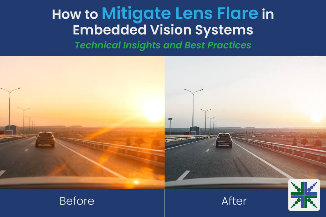
In embedded vision applications, lens flare can significantly degrade image quality and affect system reliability. This hinders the ability to obtain accurate information, which is essential for making real-time decisions. When a bright spot appears in an image, any information within that area is often lost, making it difficult to accurately process the scene.
Lens flare occurs when non-image-forming light is scattered or reflected within the optical system, resulting in unwanted artifacts. These artifacts can take the form of a hazy overlay, reduced contrast, or rings and circles of various colors, depending on the light source and lens characteristics. While lens flare is a known challenge, it can be identified by its shape patterns and minimized through best practices.
Let’s explore what lens flare is, and then practical ways to reduce or eliminate it—ultimately helping you enhance image quality in embedded vision systems.
What Is Lens Flare in Embedded Vision?
Any light that is scattered or reflected unintentionally within the optical path is considered flare. This stray light can originate from internal reflections of various components, such as lens elements, the sensor surface, the barrel, the camera enclosure, mechanical parts, filters, or even the protective cover glass.
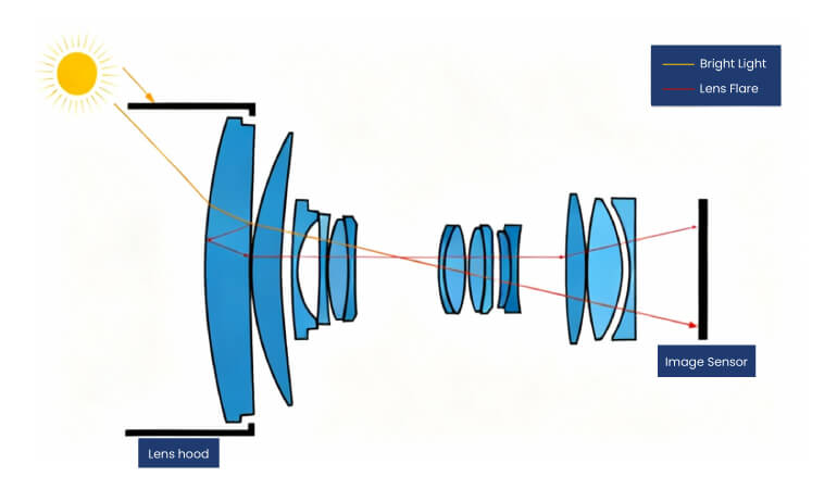 Image 1: Off-axis bright light causes internal reflections (lens flare) within lens elements
As you can see in the above image, regular light rays (orange) from the sun follow their normal path, directly reaching the image sensor. In contrast, some light rays (red) are reflected off lens surfaces, resulting in noticeable flare.
Sometimes, light rays originating from sources outside the field of view (FOV) can still enter the optical system, reflecting or scattering within the lens elements, which results in lens flare.
The image below shows stray light entering outside the lens’s FOV.
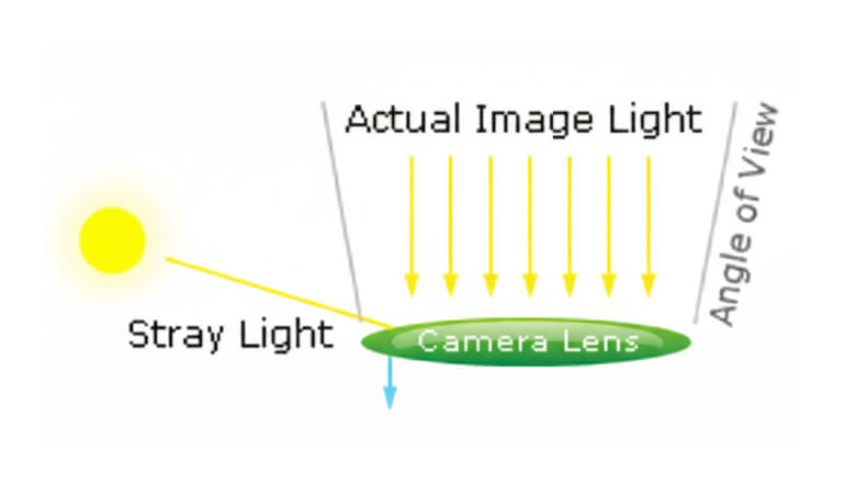 Image 2: Stray light from outside the camera’s angle of view
The Root Causes of Lens Flare
Flare is rarely caused by a single issue. It is typically the result of intense light exploiting the physical vulnerabilities of an optical system. The primary causes include:
- Internal Reflections: Camera lenses are not single pieces of glass; they consist of multiple glass elements. This creates numerous air-to-glass surfaces for light to bounce off. Furthermore, if the internal surface of the lens barrel is not treated with a black coating, stray light will bounce off the mechanical housing as well.
- Dust and Physical Damage: Imperfections such as oily smudges, accumulated dust, or microscopic scratches on the glass elements physically alter the path of incoming light. Instead of passing through cleanly, light scatters across these imperfections, creating a foggy screen that drastically reduces the overall contrast of the frame.
- Sensor Mirroring: A challenge in digital imaging comes from the sensor itself. Highly reflective silicon wafers in digital sensors can bounce incoming light backward. This light hits the rear element of the lens and is reflected right back onto the sensor for a second time, creating distinct artifacts.
- The Angle of the Light: Flare is most aggressive when bright light hits the lens at extremely steep angles, right at the very edge of the frame (referred to as off-axis light).
How Stray Light Degrades Image Quality
Stray light fundamentally damages the mathematical integrity of an image. Depending on the type of flare generated, it alters specific image quality parameters. The types of flare are explained in the sections below.
1. Veiling Flare
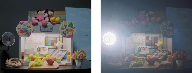
The veiling flare is caused by scattered internal light when a bright light source, such as the sun, is outside the angle of view, but its rays reach the front portion of the lens. It causes a low-contrast haze that washes out darker areas of the image, reducing contrast.
This scattered light creates a hazy overlay across the entire image, leading to a noticeable loss of contrast across the entire frame. This haze directly affects the following key image quality metrics:
- Global Contrast & Dynamic Range:
The hazy offset in dark regions makes it look like it raises the noise floor in dark areas; it reduces the global contrast of the frame, which subsequently crushes the usable dynamic range of the system.
The image below shows that the very bright light source induces a hazy effect throughout the frame called veiling glare, disrupting the contrast and washing out most of the midtones, affecting the HDR performance of the camera.
- Sharpness (MTF): The haze damps the amplitude of transitions between dark and bright regions, which measurably lowers the Modulation Transfer Function (MTF), resulting in a soft, unsharp image.
2. Streaks Flare
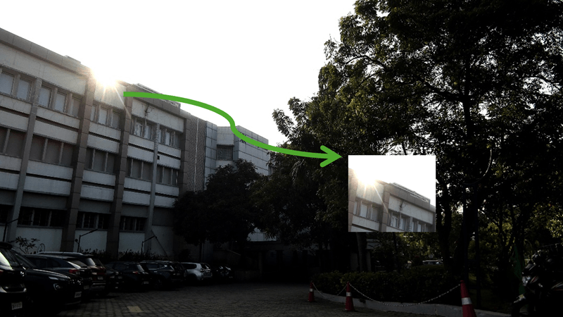
Streaks stretch the bright pixels in a specific path across the image. The streak shapes can be like a ring, usually originating from the bright object in the frame.Unlike the global haze of veiling glare, streaks severely impact local contrast, primarily in the areas immediately surrounding bright objects. This alters fine details near the bright region and heavily compromises the overall dynamic range of the scene.
The image below shows how strong light hitting a dusty or fingerprinted lens surface creates streaks. This scattering produces streaks that propagate across the image, degrading local contrast and pixel detail.
3. Ghosting flare
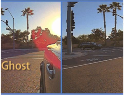
Ghosting flare differs from veiling flare in that it produces distinct visual artifacts within the image. It occurs when a bright light source, either inside or near the field of view, reflects off multiple lens elements or surfaces inside the optical system.
These internal reflections appear as clearly defined shapes, typically rings, circles, or multi-colored spots, depending on the number of lens surfaces involved and their coatings. Unlike the soft haze caused by veiling flare, ghosting flare is more localized and structured, often mimicking the shape and pattern of the internal lens configuration.
The image below shows the ghost flare:
Best Practices of Flare Testing: What Works and What Doesn’t
Simulating lens flare accurately is challenging because most flare artifacts arise from real-world imperfections such as manufacturing tolerances, surface polishing inaccuracies, and coating inconsistencies. These factors are hard to model precisely using simulation software.
To determine whether the level of flare in an optical system is acceptable, a controlled testing setup is required, involving:
- An image sensor with a defined size
- A light source with defined intensity
- Lens model with known surface reflectivity
The testing should include multiple incident angles, light sources, and wavelengths (across the visible or IR spectrum, depending on application) to cover typical operating conditions.
Metrics to Assess Flare
The S-Ratio (Scattering Ratio) and E-Ratio (Encircled Energy Ratio) are commonly used metrics. These provide a quantitative measure of the amount of unwanted light present in an image compared to the total amount of useful light.
But these metrics alone are not fully conclusive when it comes to assessing the flare. Because it assumes an improper optical surface with more scratches, and also, light sources are simplified and are not modeled accurately. It ignores migration details like the sensor’s crosstalk and the sensor’s reflectance. This level of flare evaluation can be helpful for initial flare sanity.
Flare Mitigation in Embedded Cameras
Optical design considerations
- Reduce the number of refractive surfaces to minimize internal reflections
- Choose doublets or aspheres strategically to reduce stray paths
- Optimize lens curvature and spacing to avoid direct back-reflection paths
- Use low-reflection sensor cover glass or apply internal AR coatings
The AR coating is optimized for the system’s operating spectral band (e.g., visible 400–700 nm, NIR 850 nm)
- Choose coatings with low average reflectance (Ravg < 0.25%) and low peak reflectance (Rmax < 0.5%). Typically, Ravg is 0.5% and Rmax is 1%, which are industry standards.
- Coatings should withstand humidity, temperature shifts, and mechanical wear
Mechanical design considerations
The barrel is made of metal or plastic. Metals such as aluminum are anodized, meaning that they are coated with black. The amount of reflection from the black also counted. The minimum amount of reflectance material should be chosen.
- Avoid shiny or reflective surfaces inside the lens barrel or housing
- Consider using shields or hoods to limit off-axis light
e-con Systems Advances Embedded Vision Through Smart Flare Mitigation
Since 2003, e-con Systems has been designing, developing, and manufacturing embedded vision cameras. Our engineering process includes controlled flare testing under real-world conditions, guided by industry standards such as IEEE P2020–2024, to ensure reliable and consistent image quality. Additionally, our camera domain experts validate image performance throughout the development process, ensuring that each camera is optimized for practical scenarios.
We also offer a range of HDR cameras equipped with custom development kits based on platforms such as the NVIDIA Jetson family, Qualcomm, and others. These cameras perform reliably in challenging lighting conditions—from bright daylight to dark night environments.
Housed in rugged enclosures rated up to IP69K, they provide maximum protection against dust, water, and extreme weather conditions, making them ideal for outdoor and industrial applications.
Use our Camera Selector to find your cameras quickly and easily!
To get expert support on camera integration for your vision applications, please write to camerasolutions@e-consystems.com with your requirements.

Prabu is the Chief Technology Officer and Head of Camera Products at e-con Systems, and comes with a rich experience of more than 15 years in the embedded vision space. He brings to the table a deep knowledge in USB cameras, embedded vision cameras, vision algorithms and FPGAs. He has built 50+ camera solutions spanning various domains such as medical, industrial, agriculture, retail, biometrics, and more. He also comes with expertise in device driver development and BSP development. Currently, Prabu’s focus is to build smart camera solutions that power new age AI based applications.