



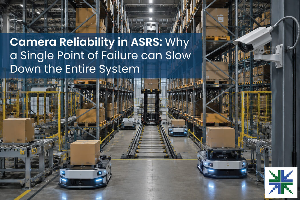
In ASRS, any camera failure rarely appears as an obviously visible hardware issue. Instead, it shows up inside the automation flow, where the control system needs visual confidence before clearing the next movement, handoff, placement, or recovery step. The camera may be a small part of the machine, but the information it provides has a large role to play in decisions that drive tasks like storage and retrieval moving.
That is why camera reliability deserves early attention in ASRS design. A weak image stream, an unstable connection, sustained vibration, EMI, or poor camera placement can turn a local sensing issue into missed detections, barcode no-reads, or a wider operational pause that ends in system downtime.
The system may still know the planned route, inventory record, and task sequence, but it loses the real-time visual confirmation needed to proceed with confidence.
This is the major risk for those building robot-led ASRS. Their reality is that the lack of camera reliability affects uptime because it hinders the ability to execute crucial tasks quickly and seamlessly.
Let’s explore the impact of cameras on the ASRS perception chain, the effects of vibration and EMI, and how selecting the right camera interface can improve system reliability.
Where Do Cameras Exist in the ASRS Perception Chain?
Modern ASRS designs depend on tightly coordinated motion because robots navigate within fixed grids, modular cells, aisles, lifts, induction stations, picking stations, or shuttle lanes. The physical system may vary, but the perception burden is similar. It must know where assets are, how they are oriented, what condition they are in, and whether the next motion can proceed.
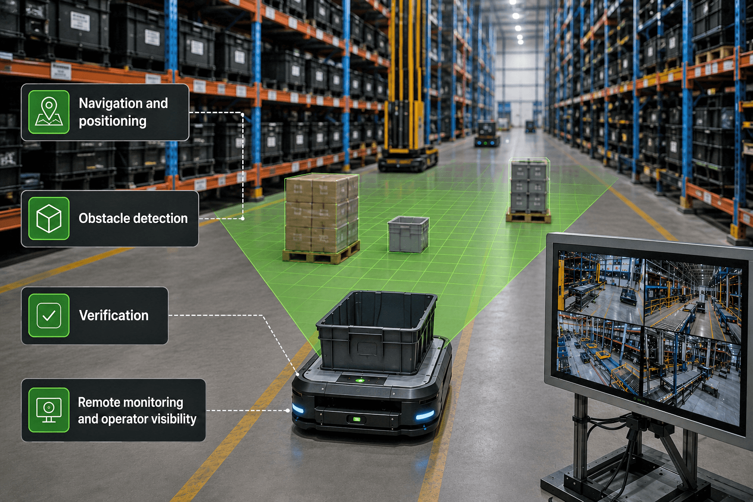
Navigation and positioning
In robot-driven storage systems, visual input can support localization, docking, alignment, and movement verification. Cameras help the system confirm that a bot, bin, tote, or load is where the software expects it to be. In a dense grid or cell-based architecture, even a small positioning gap can create a downstream exception because every move is linked to another one.
Obstacle detection
ASRS environments contain moving robots, fixed structures, maintenance activity, loose material, variable packaging, and occasionally unexpected items inside motion paths. Cameras, 3D sensors, or multi-camera modules help detect objects that may escape a purely mechanical or map-driven model. This is important around transfer points, workstations, shared zones, and areas where automation interacts with human activity.
Verification
A storage or retrieval event is only complete when the system can trust the outcome. Cameras can confirm placement accuracy, bin presence, load condition, tote orientation, barcode visibility, package shape, or pick success. This prevents small visual errors from becoming inventory errors, missed picks, damaged goods, or avoidable manual checks.
Remote monitoring and operator visibility
Operators need visual context when a cell, shuttle, bot, lift, or station enters an exception state. Camera feeds help supervisors inspect blocked areas, validate recovery steps, and reduce physical entry into automated zones. In facilities built for high throughput, this observability shortens the gap between detection and recovery.
What Vibration and EMI Actually Do to ASRS Camera?
Vibration and EMI don’t work that way. When they kill a camera outright, it becomes clear. But the hard part is when they move it out of specification, and it keeps streaming.
Vibration
Sustained vibration can disturb camera alignment, loosen mounts or mechanical connections, and weaken connector retention over time. The camera may continue streaming while its viewing angle changes, its link drops frames intermittently, or its data transfer rate reduces.
These changes can lead to:
- Blurred or misaligned frames that affect obstacle detection and load verification
- Intermittent frame loss when connector retention weakens
- Barcode no-reads or incorrect reads at picking and transfer points
- Repeated exception handling when the system cannot confirm placement or movement
- Downtime across connected cells, grid sections, lifts, or stations when a local feed becomes unreliable
IEC 60068-2-6 vibration testing assesses how camera assemblies, mounts, connectors, and cables respond to sustained sinusoidal vibration. It checks for changes in camera alignment, mechanical retention, link continuity, and data transfer rate before deployment.
EMI
Electrical spikes from motors and switches can enter the data line, causing dropped or corrupted frames or a camera link that resets during operation. Static discharge at a connector can also reset the link, interrupt communication, or damage the camera interface.
These failures may leave a robot without usable visual confirmation even when the fault appears intermittently. The result can be a missed detection, a barcode no-read, failed verification, or a pause while the control system waits for a trustworthy feed.
EN 55024:2010 provides the wider immunity framework, while the relevant EN 61000 tests cover:
- EN 61000-4-2:2009 for electrostatic discharge at +/- 4 kV contact and +/- 8 kV air
- EN 61000-4-3:2006 for radiated radio-frequency electromagnetic field immunity
- EN 61000-4-4:2012 for electrical fast transient and burst immunity, tested with the intended 3 m USB 3.0 cable
- EN 61000-4-6:2014 for conducted disturbances induced by radio-frequency fields
Why Camera Reliability Is a System-Level Design Decision
When the feed becomes unreliable, the automation flow may slow down, stop, or enter exception handling because it lacks the visual confirmation required for the next action. So the system may still receive a feed, but the feed may be unsuitable for reliable machine interpretation. That creates several functional risks, such as:
- A robot may pause because the camera misses an obstacle or cannot confirm a safe path
- A placement event may enter exception handling because vibration-related blur prevents reliable load verification
- A picking station may slow down or route the wrong item because a barcode is read incorrectly
- A remote operator may lack the visual proof needed to clear a fault
- A local camera or link fault may trigger downtime across connected cells, grid sections, lifts, or stations
Hence, camera reliability can’t be treated as a peripheral design choice. In ASRS, when perception becomes uncertain, automation must choose between slowing down, stopping, and acting with reduced confidence.
Advantages and Deployment Considerations of MIPI, GMSL, and Ethernet Interfaces
Interface selection determines how the camera is positioned, how image data reaches the processor, and how the link responds to the ASRS environment. MIPI, GMSL, and Ethernet support different integration requirements.
MIPI CSI-2
MIPI CSI-2 provides a direct, high-bandwidth path from the image sensor to the processor. It supports low-latency transfer, compact camera integration, multi-lane image streams, lower-power camera paths, and direct connection to embedded processors. Its short-link design works well when the camera and processor are close together, such as inside a robot, sensor module, or tightly packaged station device.
GMSL
GMSL supports longer camera placement and single-cable power and data architectures. It is suited to robots or storage systems where the camera is positioned farther from the processor or where cable routing passes through EMI-heavy areas.
Ethernet
Ethernet works well when distance, network integration, and remote camera placement have greater priority. It supports distributed camera placement across stations or cells where image data must travel farther before reaching compute.
ASRS camera links may run near motors, drives, charging systems, metal frames, high-speed signaling, power rails, and dense wiring. A camera that works on a bench can perform differently after integration inside a moving robot or storage cell, making cable length, routing, shielding, grounding, and connector retention part of the interface decision.
Whichever interface is selected, the integrated camera link should be validated against EN IEC 61000-6-2 for industrial immunity before deployment. The validation should include:
- EN 61000-4-2 for electrostatic discharge
- EN 61000-4-3 for radiated radio-frequency electromagnetic fields
- EN 61000-4-4 for electrical fast transients and bursts
- EN 61000-4-6 for conducted radio-frequency disturbances
Build for Degraded Vision, Then Build to Prevent It
A reliable ASRS vision layer needs two design approaches working together. The first is fault awareness. The second is failure prevention.
Fault awareness means the system can detect when visual input has become unreliable. A camera subsystem should surface dropped frames, exposure issues, link instability, temperature change, ISP errors, sync loss, and image-quality degradation before those issues can impact warehouse flow. Health telemetry should feed the same operational layer that handles robot, lift, and station status.
Failure prevention begins much earlier in camera selection and integration.
Strong ASRS camera design should account for:
- Global shutter sensors for fast-moving bots, totes, shuttles, bins, and robotic arms
- Synchronized capture when multiple views must agree on position or movement
- ISP tuning for warehouse lighting, reflective packaging, shadows, labels, and mixed material surfaces
- Rugged connectors and cable retention for vibration-prone robots or serviceable modules
- Camera mounts, connectors, and cable assemblies evaluated against IEC 60068-2-6 vibration conditions
- Thermal control for cameras placed in enclosed robotic bodies or equipment zones
- EMI-aware routing, shielding, grounding, and interface choice
- EMI/EMC immunity checks covering ESD, radiated RF, electrical fast transients and bursts, and conducted RF disturbances
- Cable validation in the planned deployment setup
- Firmware stability and long-lifecycle component planning for multi-year deployments
- On-camera or edge diagnostics that help maintenance teams isolate failures quickly
- Post-test monitoring for dropped frames, link resets, image-quality changes, barcode-read errors, and missed detections
After all, an ASRS that only detects a failed camera is already late. A better system spots degradation early enough to continue the work, flag service, or maintain safe operation without letting the issue cascade.
What e-con Systems Brings to ASRS Vision Reliability
Since 2003, e-con Systems has been designing, developing, and manufacturing embedded vision solutions, ranging from OEM cameras to complete ODM platforms.
Our MIPI camera modules help teams bring high-bandwidth image data into embedded processors with low latency and small form factors. We also offer GMSL2 cameras for longer cable runs or EMI-heavy environments and global shutter cameras for fast-moving ASRS environments.
Furthermore, e-con Systems also supports camera tuning and customization across lens selection, sensor choice, ISP configuration, form factor, synchronization, enclosure needs, and platform integration. This is critical in ASRS because two systems with similar throughput goals can have very different camera reliability requirements.
Want to check out our full portfolio? Our Camera Selector Tool makes that tremendously easy!
If you need help in selecting the ideal camera for your ASRS environment, you can contact our experts by writing to camerasolutions@e-consystems.com.
FAQs
Why does camera reliability matter in ASRS?
When vibration or EMI degrades the feed, the system usually keeps running on it, because nothing flags the change. The cost appears later when the throughput doesn’t match the expected value.
Where are cameras used in the ASRS perception chain?
Cameras support navigation, positioning, obstacle detection, verification, and remote monitoring. They help confirm bot location, bin presence, load condition, tote orientation, barcode visibility, package shape, and operator visibility during exception handling.
Why are camera failures hard to recover from in ASRS?
Camera failures can be difficult to trace because the camera may still send a feed even when vibration, EMI, or link instability has made the images unsuitable for machine interpretation. The result may appear as a missed detection, incorrect barcode read, failed verification step, or intermittent system pause rather than a clearly failed camera.
Is MIPI a good interface choice for ASRS cameras?
MIPI can be a good fit for compact ASRS robots, edge AI modules, and sensing units where the camera sits close to the processor. Since MIPI links are usually short, ASRS teams need to consider cable routing, shielding, grounding, connector retention, thermal design, and EMI exposure during integration.
How can ASRS teams reduce camera-related downtime?
ASRS teams can reduce downtime by validating camera mounts, connectors, cables, shielding, grounding, and diagnostics under expected operating conditions. IEC 60068-2-6 vibration testing and the referenced EN 55024 and EN 61000 immunity tests help check how the camera system responds to vibration, ESD, radiated RF, electrical fast transients and bursts, and conducted RF disturbances before deployment.

Suresh Madhu is the product marketing manager with 16+ years of experience in embedded product design, technical architecture, SOM product design, camera solutions, and product development. He has played an integral part in helping many customers build their products by integrating the right vision technology into them.