



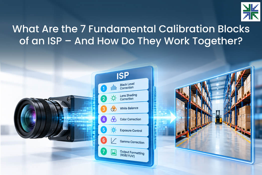
An imaging system consists of three main parts – a sensor to collect light, a lens to direct the light onto the sensor and an ISP to process the collected light as an image, just like how we, as humans, see it.
However, an image sensor does not see a clean image. Depending on the sensor, it captures either simple light intensities or alternating red, green and blue intensities. With the help of the Image Signal Processor (ISP), where the capture light goes through various blocks that are designed to perform a specific process, the output comes as we desire.
In this blog, you’ll get to know the blocks that are essential for a reasonable quality output and how the signal from the sensor is treated in these blocks to create a visually appealing output.
Seven Fundamental Blocks of an ISP
Within an ISP, most things happen in two ways – linearly and non-linearly, correction and enhancement, and RGB and YUV conversion. Even with linear cameras, the response of the pixel will be linear to the incoming light. Certain blocks need non-linear processing as part of obtaining a visually appealing image.
There are certain blocks which are fundamental, such as black level correction, lens shading correction, white balancing, color correction, exposure, and gamma.
1) Black level correction
Black level correction, or subtraction, is done to establish a floor for the dark areas, since an image sensor, even when kept in absolute darkness accumulate unwanted electrical current caused by thermal energy and sensor design. This ‘dark current’ creates an offset, making a true mathematical zero impossible.
Performing this correction subtracts the offset from every pixel. If unaddressed, the image sensor may lead to artifacts in the final output, appearing hazy and dark grey in the regions where it is supposed to be true black and at times lacking in contrast. So, it is crucial to retain the dynamic range of the scene, considering that both under/over-correction leads to artifacts.
Read: Black Level Correction in Image Sensors: What It Is and Why It Matters
Just like black level, certain ISPs do perform bad pixel correction, but not mandatory. No sensor is ideal, and neither are the individual pixels in it. Certain pixels may be unresponsive – some dead, stuck in certain values or bright all the time. This varies from sample to sample.
For machine vision applications, performing this would be suggested because having such pixels would alter how the edges are being detected. Certain ISPs perform bad or defect pixel correction by identifying such pixels and average it out with the neighboring ones.
2) Lens shading correction
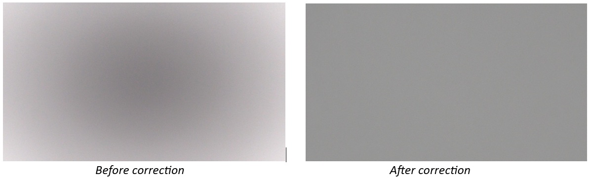
This is a stage that addresses the basic light fall-off that happens with a lens, since light rays traveling toward the corners of the sensor travel a longer distance than the ones toward the center. It causes both luminance fall-off and color shading, while the latter is more of a secondary artIfact.
This also results in the image being darker along the corners of the frame than the center, and thus spatial consistency is broken. With the help of a RAW image from the sensor, the ISP corrects for this inconsistency and provides a spatially uniform image.
Read: What is Lens Vignetting in Embedded Cameras?
3) White balance
Real-world scenes have multiple varying lights emanating from different areas. During late evening, you could see the Sun in its warm orange tone spreading across the sky and streetlamps with cool blue lights illuminating the streets. That is a difficult scenario for an imaging system to identify and reproduce the neutral colors as they are, along with the other colors across the scene.
The human brain automatically identifies and observes white as white. Still, for an imaging system, the ISP should provide the information and balance the color R, G and B channels to properly do that. And for that, the auto white balance block dynamically analyses the frame, identifies the color temperature and applies the gain to the red and blue channels relative to green, eradicating the color cast.
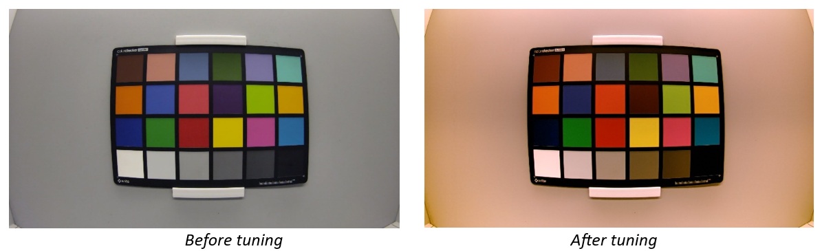
The above image perfectly captures the difference between before and after tuning of an ISP, which properly discards the color casts caused by warm lights in the scene. There are sophisticated ISPs which have internal ‘modes’ within them to identify the scenes based on the statistics that they get – such as outdoor blue sky, outdoor green, night outdoor and so on.
These kinds of statistics will help in getting more accurate data as output.
4) Color correction
Now that we have identified the color temperature of the scene and removed the color cast, there are individual colors which are to be properly reproduced as they are present in the real world. Since white balance balances the R, G and B channels relative to each other, it doesn’t solve the channel crosstalk.
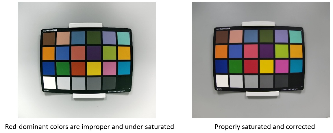
To solve that, the ISP has an intrinsic matrix, one or multiple depending on the capability of the ISP, which corrects the colors and saturation to make it close to the ideal. If improperly calibrated, this would result in erroneous data as output. The example below shows two almost properly white balanced image but the left one has certain colors not properly reproduced, patches containing a high amount of red component, and is less saturated compared to the one on the right, which is corrected for the same.
5) Gamma
This block can be said to be the mid-point of any ISP. Whatever we have done till now are corrections, and anything next to this would be an enhancement. Considering we have dealt with linear output till now, this must be modified such that we can perceive the image luminance as in the real world, since our eyes perceive brightness non-linearly. We are highly sensitive to changes in dark regions compared to the bright regions.
So, Gamma is a static display standard non-linear curve that compresses data such that it is appealing to look at. Otherwise, the linear output will be dark and flat.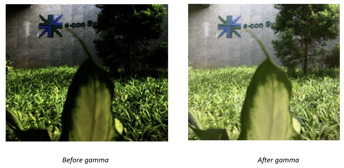 The above is an exaggerated example of the impact of fine tuning since some more parameters like auto-exposure are also adjusted to arrive at the output. Keep in mind that gamma is applied for visual perception, and a pleasing image doesn’t mean it has all the information intact.
Even this one has compressed data which aren’t for the eyes. Machine vision applications may not prefer this output if heavily compressed or done. Even for visual inspection, improper handling of gamma would cause artifacts.
Read: What Is Gamma Correction and Its Importance in Embedded Vision?
Now to the other basic correction blocks and their trade-offs, which happen if we are to prioritize one specific part of image quality parameters. These decisions should be taken based on the use case and end application.
There is no single tuning or calibration that satisfies all applications and requirements. An application may require the device to have some amount of visibility under extreme low-light conditions. Either one has to choose a sensor that could perform this task or be ready to accept the trade-offs that come if we enhance the performance by amplifying the signal in the ISP.
By doing the latter, we should face increased noise, and if trying to suppress it by performing noise reduction, be ready to sacrifice sharpness for that.
6) Tone mapping
Gamma compensates for our eye’s non-linear perception of light and is global and static. Tone mapping is dynamic and, at times content aware based on which part we are talking about. Global and local tone mapping blocks will be present in ISPs. This is handled when one must preserve clipping in bright areas, lift details in the shadows, based on the scene’s content, lighting, neighboring pixels and at times for all the said purposes.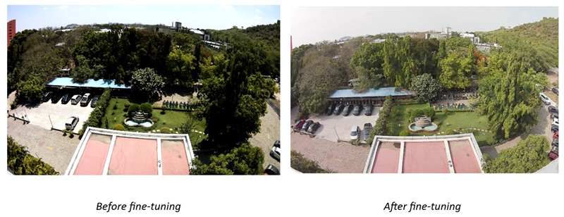
The above images depict the scenario where all the said cases are being addressed. The bright regions are toned down a bit; details are enhanced in the dark areas and shadows. The dynamic range of the scene is also preserved better after tuning, and, of course, compression of the data in certain areas would have occurred; this can be concluded by performing a quantitative analysis of the tuning.
Sharpening
Sharpening is done to restore the crispness of an image, and it is done to enhance the mid- and high-frequency details which are softened due to lenses and filters, unintended smoothening, etc. It amplifies the local contrast in an image, thereby making the text, edges or boundaries noticeable.
Certain advanced ISPs perform directional filtering and enhancement where it locates the angle of transitions and boosts along that. Some deliberately over-sharpen the image to make it visually appealing.
At times, too much over-sharpening or processing would lead to artifacts along the edges – glowing halos and high-contrast boundaries. By doing this, it boosts the underlying noise, thus making the textures get buried under it. Machine vision applications discard or misinterpret heavily processed output.
Some ISPs split the captured frequencies – low, mid and high- and perform the processing for the required areas. Usually, low frequencies don’t need to be enhanced, as those will be properly rendered. Enhancing the color channel will induce Chroma artifacts, so it’d be restricted simply to the luminance channel.
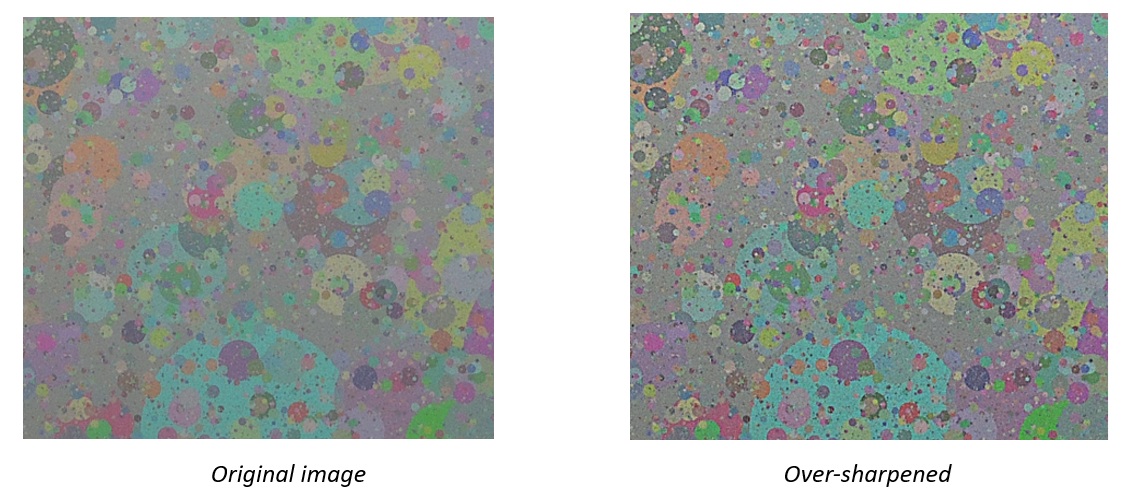 The above example clearly depicts the impact of over-sharpening the image to enhance the high-frequency details. By doing so, one can see how random artifacts and overshoot along the edges appear. If one still needs details, the artifacts arising from this should be tolerated.
7) Noise reduction
Noise is generated from the incoming light to the heat generated by the hardware. The incoming light isn’t structural or definitive; they are random, and that’s the very first source of noise. With respect to the device, heat generates noise, and then amplification of the signal done by applying gain in the ISP boosts noise.
This accumulated noise is hard to eradicate completely without any sort of trade-offs. And the noise is also spatial – varying within different areas of a frame, and temporal – varying between frames.
Several ISPs have blocks for both spatial and temporal noise negation of it. Some do this in the raw domain itself – both 2D, which is spatial and 3D, which is temporal. By doing so at this level of the imaging system, it helps in reducing the predictable noise, which includes shot noise, read noise, and more. It can minimize the amount of Chroma/color noise that occurs in the output image.
With respect to 3D raw domain noise reduction, it can reduce motion artifacts. If we let noise through the other blocks, we lose predictability, as later blocks in the processor work non-linearly.
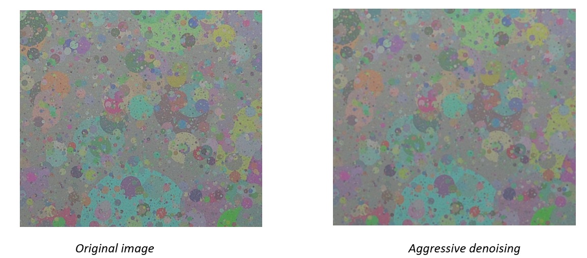
The above example images, of a random pattern test chart, show the impact of aggressive denoising on high frequencies, i.e., textures. Though the original image has some noise in high-frequency regions and a lot of details in a small area, trying to reduce that noise aggressively, as done in the image on the right, would lose sharpness in those regions.
These decisions are made considering which one should be prioritized. The processing would improve the SNR of the image, and that may look good on paper, the output, when looked at lack details at high frequencies.
Conclusion
The blocks that we saw till now can be considered fundamental and minimal. For effective output and functioning of an imaging system, each block needs dedicated attention during tuning and understanding of its purpose in the pipeline.
There is no system without a trade-off. Sometimes it is explicit at the output; sometimes not. Many times, we do not worry about the trade-offs if the intended problem is solved.
But getting to know what is happening inside the pipeline will help in understanding where to go with the current state of functioning rather than moving about randomly and making favorable decisions.
e-con Systems’ Unparalleled Camera Tuning Expertise
Since 2003, e-con Systems has been designing, developing, and manufacturing embedded vision solutions, from custom OEM cameras to complete ODM platforms. Our camera tuning and IQ expertise helps deliver strong image quality from sensor to final output, ready for real-world applications.
We offer TintE™, an FPGA-based Image Signal Processor with a complete ISP pipeline and customizable blocks such as black level correction, debayering, AWB, AE, and gamma correction.
Use our Camera Selector to browse our full portfolio of camera solutions.
You can also connect with our imaging experts to discuss your camera requirements. Please write to camerasolutions@e-consystems.com.
FAQs
- What are the fundamental calibration blocks inside an ISP?
Core ISP blocks include black level correction, lens shading correction, white balance, color correction, exposure, and gamma. Together, they process sensor data so the resulting image has suitable brightness, color reproduction, and tonal response.
- How do black level correction and lens shading correction improve image quality?
Black level correction removes the electrical offset produced by the sensor in dark regions, helping preserve true blacks and contrast. Lens shading correction compensates for luminance fall-off and color shading toward the edges of the frame, producing a more spatially uniform image.
- What is the difference between white balance and color correction in an ISP?
White balance adjusts the red and blue channels relative to green based on the scene’s color temperature, reducing unwanted color casts. Color correction then uses a matrix to address channel crosstalk and improve individual color reproduction and saturation.
- How are gamma correction and tone mapping different?
Gamma uses a static, global nonlinear curve to make luminance appear closer to human visual perception. Tone mapping works dynamically and can respond to scene content by controlling bright regions and lifting shadow detail.
- Why do sharpening and noise reduction require trade-offs during ISP tuning?
Sharpening boosts local contrast and restores mid- and high-frequency detail, but aggressive processing can introduce halos, amplify noise, and create edge artifacts. Noise reduction suppresses spatial or temporal noise, though stronger denoising can remove fine texture and reduce sharpness. The choice depends on which image characteristics matter more.

Arun is a seasoned Embedded Vision leader with 11+ years of experience driving innovation in robotics and AI-powered imaging systems. He focuses on developing perception stacks that power intelligent robotic systems, bridging hardware, algorithms, and edge deployment.