

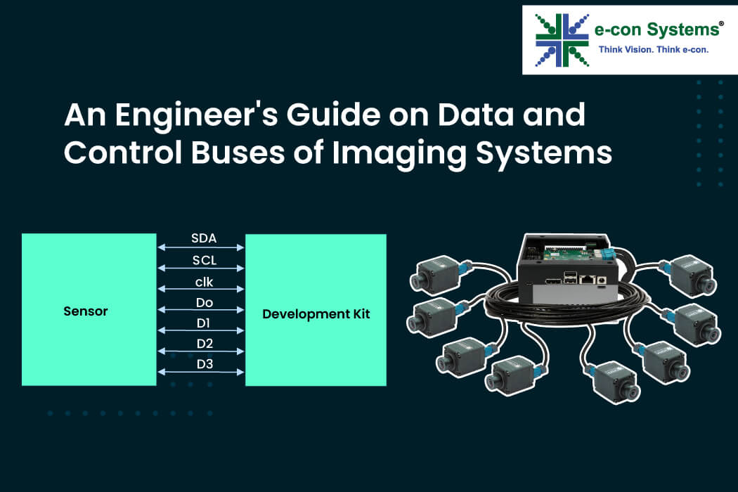
The communication architecture within a camera is important in enabling efficient data exchange between the image sensor and the host processor. It is built on two fundamental transport protocols: the Control Bus to control communication between the camera and the image sensor, and the data bus to transmit image pixel data.
Imaging systems are significantly improving as a result of the development of communication techniques. Over time, complex serial interfaces with multi-gigabit transmission speeds replaced conventional parallel interfaces with a large number of pins and constrained bandwidth. Through the capability of high data bandwidth processing, it delivers a high-quality image, which is crucial in applications that often deal with high-resolution data.
The integration of data and control buses enables multi-camera synchronization, which is crucial in applications that rely on simultaneous capture from multiple viewpoints—for example, in sports broadcasting, delivery vehicles, and surround-view systems.
In this blog, we’ll see what control and data buses are, their features, and how they effectively transmit data to achieve higher resolution and frame rates, providing high-speed imaging from multiple angles.
Understanding Control Buses in Imaging Systems
What is a Control Bus?
The control bus is a communication pathway that allows the camera’s processor to manage and control various functions of the camera. This includes adjusting settings like exposure, gain, trigger, and other operational parameters.
It is responsible for configuration, synchronization, and control signaling between components. The two principal control bus technologies in imaging systems are I²C (Inter-Integrated Circuit) and its advanced successor, I³C (Improved Inter-Integrated Circuit).
I²C (Inter-Integrated Circuit)
I²C is one of the most widely implemented control bus protocols in imaging systems. It is a multi-master communication.
The key features of I²C are:
- Multi-master communication architecture – It allows multiple devices to initiate transfers
- Two-wire serial communication protocol – The SDA (Serial Data Line) for bi-directional data transfer and SCL (Serial Clock Line) for timing synchronization
- Addressing scheme – It supports multiple slave devices on a single bus
Below is the image of the I²C block diagram.
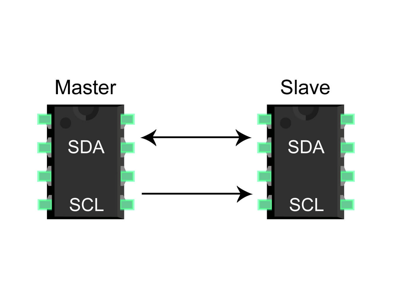 Figure 1: I²C block diagram
The straightforward implementation of I²C makes it ideal for the configuration and control of image sensors, but its limited bandwidth constrains its application for high-speed data transfer requirements.
I³C (Improved Inter-Integrated Circuit)
I³C (also known as Sensewire) represents a significant advancement over I²C while maintaining backward compatibility.
Below is the image of the I³C block diagram.
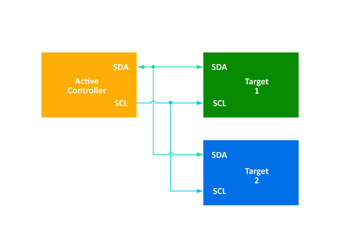 Figure 2: I³C block diagram
The key features of I³C are:
- Higher bandwidth – supporting significantly faster data rates than I²C
- In-band interrupt (IBI) – avoiding the separate interrupt lines
- Dynamic addressing – enabling flexible device identification without hardcoded addresses
- Hot-join capability – supporting plug-and-play functionality
- Advanced power management with low-cost wake mechanisms
- Multi-master, multi-slave support with improved arbitration
These enhancements make I³C particularly suitable for high-speed embedded applications where power efficiency and simplified interconnections are critical design considerations.
Now that you understand the control bus and its advantages and limitations in camera data processing, let’s explore the data bus and its key technological enhancements for the imaging system.
Understanding Data Buses in Imaging Systems
What is a Data Bus?
The Data Bus is a communication pathway that transfers image data from the camera’s image sensor to the processor. It handles the high-bandwidth transmission of image data. They are categorized into parallel interfaces (CPI) and serial interfaces (CSI).
Camera Parallel Interface (CPI)
The Camera Parallel Interface (CPI) is a type of camera interface used to connect image sensors to processors. It uses multiple parallel data lines. For example, a data bus uses each line to transfer specific bits. Consequently, separate lines are required for each bit. This allows for higher data throughput, making it suitable for applications requiring high-speed image capture and processing.
Key technical characteristics of CPI include:
- Multiple dedicated data lines (typically 8, 10, 12, or 16 bits wide)
- Additional control signals, including HREF (Horizontal Reference) and HSYNC (Horizontal Sync)
- SDR (Single Data Rate) operation sampling one data value per clock cycle
- Clock speeds typically not exceeding 40-50 MHz
For an RGB565 pixel format (16-bit representation):
On 8-bit parallel interface, one clock cycle is used to transmit 8 bits of data, then 2 pclk is required to transmit 16 bits of a pixel.
The maximum theoretical data rate for CPI is calculated as:
Data Rate = Number of Data Lines × Clock Speed
For a 16-bit wide interface at 50 MHz:
Maximum Data Rate = 16 bits × 50 MHz = 800 Mbps
This translates to approximately 162 FPS for a 640×480 resolution with RGB565 encoding:
Each frame contains 4,915,200 bits (640 x 480 × 16).
The FPS can be calculated as
800 Mbps ÷ 4,915,200 bits = 162 FPS
High frame rates and high-resolution images can be handled by Camera Parallel Interface configuration. Still, because it requires exact timing and synchronization across all the parallel lines, it may be more difficult to accomplish.
MIPI CSI (Camera Serial Interface)
The MIPI Camera Serial Interface (CSI) is used to connect cameras to processors in embedded applications. It uses high-speed serial links for image data transmission that reduces pin count while significantly increasing bandwidth. CSI-1, CSI-2, and CSI-3 are the different forms of CSI. Of these, CSI-2 is the one that is most frequently used in cameras.
Technical Specifications of CSI-2
Physical Medium: In the CSI-2, there are a lot of physical mediums. The most common are D-PHY, supporting up to 2.5 Gbps per lane, and C-PHY, supporting up to 2.5 Gbps per lane.
DDR (Double Data Rate) The Camera Serial Interface (CSI) supports Double Data Rate (DDR), which means that two data bits can be read per clock pulse. This capability enhances data transmission efficiency, allowing higher data rates and improved performance in high-speed imaging applications.
Multiple lanes: It is typically 1, 2, or 4 for parallel data transmission over serial links.
Virtual channel support: It supports up to 4 virtual channels through which up to eight cameras can be connected. This provides flexible camera configurations as well as images from different viewing areas, making it ideal for mobility applications, delivery robots, autonomous vehicles, agricultural vehicles, mining vehicles, and all-terrain vehicles (ATVs).
So far, we have explored the two primary types of data buses used in imaging systems: the Camera Parallel Interface (CPI) and the Camera Serial Interface (CSI). Let’s now see a quick comparison between the traditional parallel interface and the advanced serial interface.
Comparative Analysis: Parallel vs. Serial Interfaces
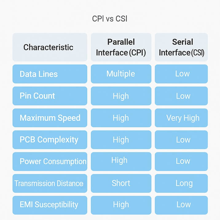
e-con Systems’ cameras increasingly favor serial interfaces over traditional parallel approaches due to their higher-bandwidth solutions, multi-synchronization characteristics, simplified interconnection requirements, and I²C control bus due to its low pin count and ease of integration.
e-con Systems Offers Multi-Camera Solutions for High-Speed Embedded Applications
Since 2003, e-con Systems has been at the forefront of designing, developing, and manufacturing cutting-edge camera solutions. Our deep expertise in imaging technology ensures that we carefully evaluate and integrate the best communication protocols to satisfy the unique requirements of every application, delivering synchronized multi-camera setups with high-speed data transfer, high resolution, and exceptional image quality.
For details on camera setups ranging from one to eight cameras, paired with powerful custom development kits like those from NVIDIA®, Qualcomm, and more, visit our Synchronized Multi Camera Solutions for NVIDIA, TI & Qualcomm.
To explore our full range of cameras built with advanced imaging technologies, visit our Camera Selector Page.
For expert guidance on selecting the camera solution, reach out to us at camerasolutions@e-consystems.com

Prabu is the Chief Technology Officer and Head of Camera Products at e-con Systems, and comes with a rich experience of more than 15 years in the embedded vision space. He brings to the table a deep knowledge in USB cameras, embedded vision cameras, vision algorithms and FPGAs. He has built 50+ camera solutions spanning various domains such as medical, industrial, agriculture, retail, biometrics, and more. He also comes with expertise in device driver development and BSP development. Currently, Prabu’s focus is to build smart camera solutions that power new age AI based applications.