

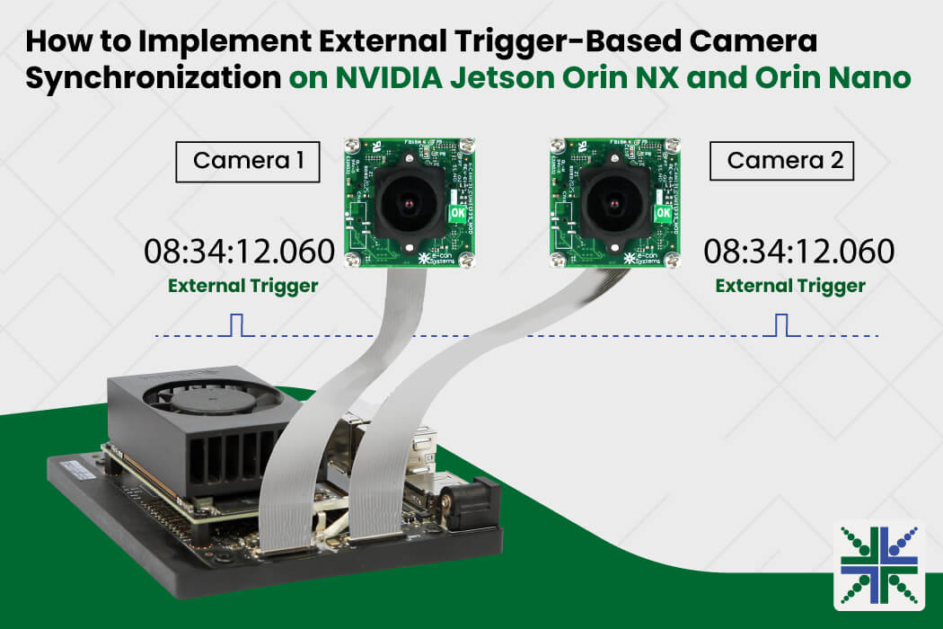
Image synchronization is essential in embedded vision applications that require precise, simultaneous capture across multiple cameras. These cameras use external triggering to capture images at the same moment when a specific event occurs, such as an object reaching a target position on a conveyor belt.
The synchronized image improves inspection accuracy and reduces motion blur in embedded vision systems used in use cases such as industrial automation and robotics.
In this blog, we demonstrate how to implement camera synchronization using an external trigger generated through the GPIO pins of the NVIDIA Jetson Orin NX and Orin Nano Developer Kits.
Why Does Camera Synchronization Matter?
Each camera operates independently, using its own internal clock, and streams frames continuously in free-running mode. There is no control over when each frame is captured. For many applications, this is sufficient. Surveillance, traffic monitoring, and parking-lot management are common examples where free-running mode works well.
Typically, free-running mode does not control the frames. If the frames are not synchronized, the captured frames may represent different moments in time, leading to mismatched images and inaccurate analysis in the systems.
An external trigger in the cameras solves this problem by capturing frames simultaneously. This implementation enables accurate dual-camera synchronization while reducing CPU utilization, bandwidth consumption, and power usage.
Understanding Embedded Camera Operating Modes
Embedded cameras operate in two modes: free-running and trigger.
- Free-running mode: The camera operates on its internal clock and streams continuously, like a surveillance camera
- External trigger mode: The camera waits for external signals before capturing each frame. For example, when an object reaches a predefined position, a trigger signal is generated, signaling the cameras to capture an image. On NVIDIA Jetson Orin NX and Orin Nano platforms, GPIO pins can be configured to generate external trigger signals for connected cameras
What you’ll need before you start:
- NVIDIA Jetson Orin NX or Orin Nano Developer Kit
- A compatible camera module (e-CAM25_CUONX used in this guide for demonstration)
- The camera’s adapter board (with an external GPIO trigger pin exposed)
- Jetson Linux with drivers already flashed on your board, following the steps in the getting started manual of the respective product.
Before making any connections, check the accepted voltage range in the datasheet for your specific camera and Jetson variant.
|
- Python 3 (comes pre-installed with most Jetson setups)
- 2 jumper wires
- Jetpack 6.2 or 6.2.1
Steps to Trigger Embedded Cameras Using the GPIO of Jetson Orin NX /Orin Nano
Step 1: Enabling GPIO PWM (Pulse Width Modulation) Pins
- Press Ctrl + Alt + T to open a new terminal on the host PC running Ubuntu 22.04.
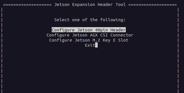
- Launch the Jetson-IO configuration utility on NVIDIA Jetson platforms.
$ sudo /opt/nvidia/jetson-io/jetson-io.py
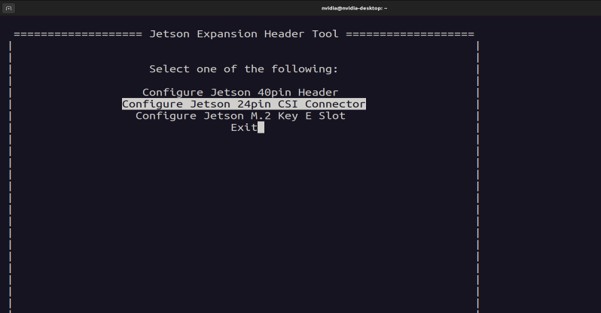
- Click Configure Jetson 40pin Header, as shown below.
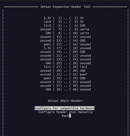
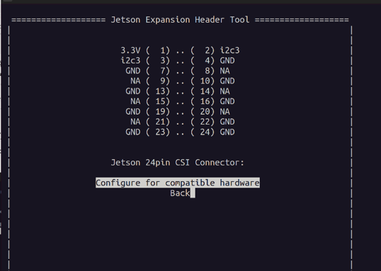
- Select Configure for compatible hardware pins, as shown below.
- Select pwm1, pwm5, pwm7 pins, as shown below.
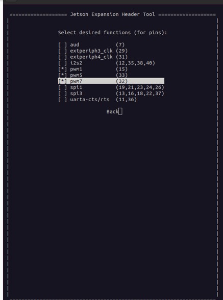 Click Back.
- Click Save pin changes.
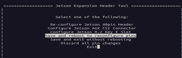
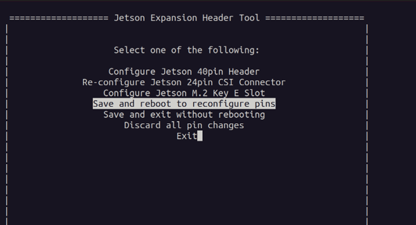
- Click Save and reboot to reconfigure pins, as shown below.
After the system reboots, the selected GPIO pins (PWM1, PWM5, and PWM7) can be used to generate PWM signals required for external trigger generation and camera synchronization.
Step 2: Connecting the Camera and Jetson Orin NX/Orin Nano Developer Kit
The procedure described in this blog has been tested and validated specifically with cameras based on NVIDIA Jetson Orin NX and Orin Nano. It has not been validated for NVIDIA Jetson AGX Orin platforms.
Connection Steps:
- Locate the CN3 connector of the camera adapter board, as shown below.
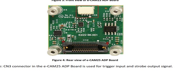
Figure 1: Camera Adapter Board
The Jetson Orin NX/Orin Nano developer kit has a 40‑pin GPIO Expansion Header, as shown below.
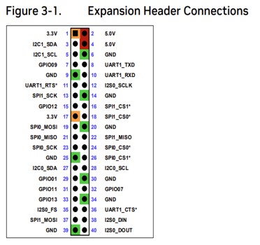 Figure 2: GPIO Expansion Header
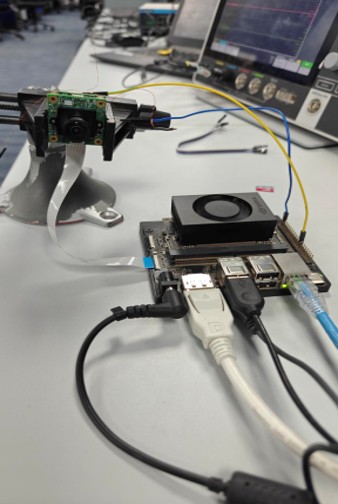
- Connect the trigger output pin 15 from the Jetson GPIO header to Pin 2 of the CN3 connector on the camera adapter board using a jumper wire as shown below.
- Connect another jumper wire from the Jetson GPIO header Pin 39 to Pin 4 of the CN3 connector as shown below.
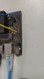
Figure 3: Jumper Wire Connected with GPIO Expansion Header
This hardware setup enables the PWM-generated trigger signal from the Jetson platform to be delivered to the camera.
Step 3: Updating Overlay File
If the drivers are already flashed, and the Jetson GPIO pins are configured, Python is typically available by default on the Jetson platform. You only need to update the overlay file by selecting the appropriate camera overlay, as described below. If not installed, refer to the respective product’s Getting Started manual for installation and driver flashing.
- Run the following command on the host PC to configure GPIO pins, PWM interfaces, and camera overlays.
nvidia@nvidia-desktop:~$ sudo /opt/nvidia/jetson-io/jetson-io.py
- Select Configure Jetson 24pin CSI Connector, as shown below.
- Select Configure for compatible hardware as shown below.
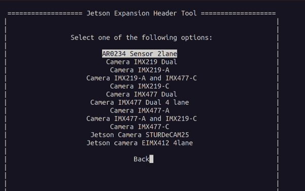
- Select the sensor which you want to use (In this case, it is AR0234 Sensor 2lane)
- Click Save Pin changes, then click Save and reboot to reconfigure pins.
After the system reboots, the camera is ready to operate in external trigger mode.
For trigger parameters and synchronization-related information, refer to the respective product’s trigger mode document from our developer website.
Step 4: Streaming Cameras
- Stream the camera in free-running mode using the e-con Systems’ eCAM_tk1 application provided with your camera driver package.
- Switch the cameras from free-running mode to External Trigger using the eCAM_tk1 application, as shown in the figure below.
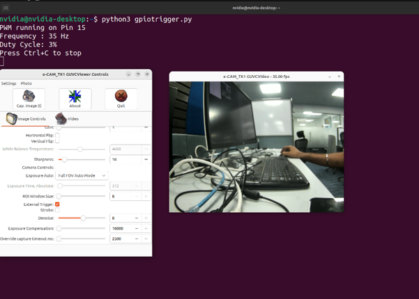
Once External Trigger mode is enabled, the camera stops operating in free-running mode and waits for an external trigger signal before capturing images.
Step 5: Generating a Trigger Pulse
To generate the external trigger signal required by the camera, the Jetson GPIO pin is configured to output a PWM signal. PWM enables precise control over the trigger frequency and pulse width.
In this demonstration, the camera is configured to support up to 120 FPS at 640 × 480 resolution.
An external trigger signal of 35 Hz with a 3% duty cycle is applied to the camera, resulting in image capture and streaming at approximately 35 FPS.
The image below shows the connection setup for the camera connected to the GPIO to provide the trigger pulse.
 Follow the steps below to generate the trigger pulse on GPIO Pin 15 at 35 Hz with a 3% duty cycle.
- Save the following script as gpiotrigger.py and run it.
import Jetson.GPIO as GPIO

import time

# Use physical pin numbering

GPIO.setmode(GPIO.BOARD)

# PWM output pin

PWM_PIN = 15

# PWM settings

FREQUENCY = 35      # Hz

DUTY_CYCLE = 3      # %

# Setup GPIO

GPIO.setup(PWM_PIN, GPIO.OUT, initial=GPIO.LOW)

# Create a PWM instance

pwm = GPIO.PWM(PWM_PIN, FREQUENCY)

# Start PWM

pwm.start(DUTY_CYCLE)

print(f"PWM running on Pin {PWM_PIN}")

print(f"Frequency : {FREQUENCY} Hz")

print(f"Duty Cycle: {DUTY_CYCLE}%")

print("Press Ctrl+C to stop")

try:

while True:

time.sleep(1)

except KeyboardInterrupt:

print("\nStopping PWM...")

finally:

pwm.stop()

GPIO.cleanup()
- Run the following command to install the GPIO library (Skip this step if it’s already installed).
sudo pip3 install Jetson.GPIO
- Run the following Python script to generate the trigger pulse.
sudo chmod +x ./gpiotrigger.py
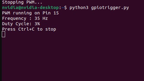
python3 gpiotrigger.py
After running the above script, the generated trigger pulse will appear on the screen, as shown below.
 To check the generated trigger pulse, an oscilloscope can be used.
The image below shows the generated 35 Hz trigger signal with a 3% duty cycle, as measured on the oscilloscope (optional).
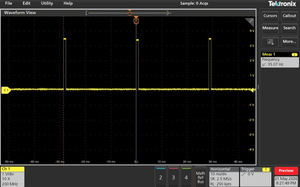 By applying the external trigger signal of 35 Hz with a 3% duty cycle to the camera, image streaming at approximately 35 FPS is achieved. Through this, synchronization between two cameras can be achieved, ensuring precise frame alignment for time-sensitive, embedded vision applications such as robotics, industrial automation, stereo vision, and intelligent transportation systems.
e-con Systems’ Trigger-Enabled Cameras for NVIDIA Jetson Orin NX and Orin Nano
e-con Systems has been designing, developing, and manufacturing OEM and ODM camera solutions. Backed by over 20 years of expertise in embedded vision, we deliver everything from custom OEM camera solutions to complete ODM platforms tailored to application-specific requirements.
We also offer a range of trigger-enabled cameras for NVIDIA Jetson Orin NX and Orin Nano platforms, enabling reliable camera synchronization for embedded vision applications.
Use our Camera Selector to find your cameras quickly and easily identify the best-fit camera.
Need help selecting the right camera or implementing synchronization for your application? Contact our camera experts at camerasolutions@e-consystems.com.

Prabu is the Chief Technology Officer and Head of Camera Products at e-con Systems, and comes with a rich experience of more than 15 years in the embedded vision space. He brings to the table a deep knowledge in USB cameras, embedded vision cameras, vision algorithms and FPGAs. He has built 50+ camera solutions spanning various domains such as medical, industrial, agriculture, retail, biometrics, and more. He also comes with expertise in device driver development and BSP development. Currently, Prabu’s focus is to build smart camera solutions that power new age AI based applications.