



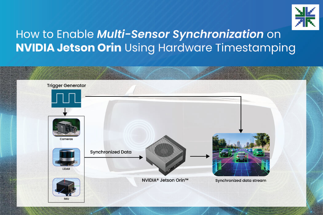
Embedded vision systems rely on data from multiple sensors, including cameras, LiDAR, and IMUs, to accurately perceive their surroundings. For reliable sensor fusion, all sensor data must be precisely synchronized.
However, conventional software timestamps are affected by system-level delays, making accurate time alignment difficult. Hardware timestamping addresses this challenge by recording the exact acquisition time, enabling precise synchronization across multiple sensors.
In this blog, we’ll share insights on the barriers to multi-sensor synchronization and go in depth into how hardware-assisted synchronization helps.
Challenges in Multi-Sensor Synchronization
Multi-sensor synchronization plays a critical role in applications such as autonomous vehicles, robotics, AMRs and Intelligent Transportation Systems (ITS), where data from various sensors must be accurately aligned. Typically, each sensor operates independently at a different frequency and uses a different buffer time. For many years, software-generated timestamps were sufficient for multi-sensor synchronization.
Timestamps generated at the application or driver level did not accurately reflect the actual sensor acquisition event. Conventional software-generated timestamps introduce inaccuracies due to software latency, operating system scheduling, interrupts, or data buffering delays.
Hardware timestamps overcome this limitation by capturing the precise timing of sensor acquisition events.
To know more about sensor fusion architecture on NVIDIA Orin NX, read: What Sensor Fusion Architecture Offers for NVIDIA Orin NX-Based Autonomous Vision Systems
What is a Hardware Timestamp?
A hardware timestamp is a precise time value generated directly at the exact moment a physical event occurs. The embedded vision system generates the hardware timestamp when it receives the hardware synchronization pulse from a trigger source. This hardware synchronization pulse is a common pulse and can be adjusted to align sensor data from multiple sensors accurately within the system.
The following figure shows the block diagrams for hardware timestamping.
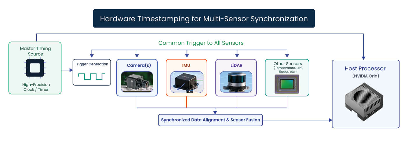 Unlike software-generated timestamps, hardware timestamping records the precise acquisition time by minimizing the latency and jitter introduced by software layers, without requiring post-acquisition timestamp correction or interpolation.
Hardware-generated timestamps provide precise acquisition timing for frames from synchronized multi-camera systems and samples from other sensors, enabling accurate temporal alignment for multi-sensor fusion. This framework simplifies multi-sensor data fusion for applications, including robotics, drones, AGVs, and 360° surround-view systems.
Hardware vs. Software Timestamp: A Quick Comparison
| Hardware Timestamp | Software Timestamp |
| Timestamp recorded at the start of exposure | Timestamp recorded when the image is read out by the driver (V4L2) |
| Represents the actual trigger event | Generated by the V4L2 driver after the frame reaches the software stack |
| Provides the true image capture time | Represents the frame reception/processing time |
| Accurately aligns with LiDAR, IMU, and other sensor synchronization data | Does not accurately align with LiDAR/IMU synchronization due to software and transfer latency |
| High precision with minimal jitter | Lower precision; affected by OS scheduling, USB/Ethernet transfer, and CPU load |
| Ideal for sensor fusion, robotics, and multi-camera synchronization | Suitable for general video streaming and applications where precise timing is not critical |
How Hardware-Assisted Synchronization Works
The key challenge in multi-sensor systems is that different sensors operate at different frequencies. In a typical autonomous driving setup:
- Cameras operate at 30 FPS — one frame every 33.3 ms
- IMUs operate at 100 Hz — one sample every 10 ms
- LiDAR operates at 10–20 Hz — one scan every 50–100 ms
To understand synchronization, consider two categories of sensors:
- Camera→ Image sensor
- IMU or LiDAR→ Non-image sensor
Depending on the operating frequencies, one of the following conditions exists:
- Camera frame rate > non-image sensor sampling rate
- Camera frame rate < non-image sensor sampling rate
To synchronize these sensors, the embedded system uses a trigger source as the master timing reference to generate a common hardware synchronization pulse and distributes it to all the sensors. It captures the hardware-generated timestamp corresponding to the hardware pulse and acquires sensor data that matches it.
The below illustrates how synchronization is achieved across sensors operating at different frequencies.
| Camera Frame | Camera (30 FPS) | IMU (100 Hz ) | LiDAR (10–20 Hz) |
| Frame 0 | 0–33.3 | 0, 10, 20, 30 | Scan at 0 ms |
| Frame 1 | 33.3–66.6 | 40, 50, 60 | — |
| Frame 2 | 66.6–99.9 | 70, 80, 90 | — |
| Frame 3 | 99.9–133.2 | 100, 110, 120, 130 | Scan at 100 ms |
| Frame 4 | 133.2–166.5 | 140, 150, 160 | — |
| Frame 5 | 166.5–199.8 | 170, 180, 190 | — |
| Frame 6 | 199.8–233.1 | 200, 210, 220, 230 | Scan at 200 ms |
| Frame 7 | 233.1–266.4 | 240, 250, 260 | — |
For example, with a camera operating at 30 FPS and a LiDAR operating at 10 Hz, the system captures about three camera frames during each LiDAR acquisition interval. The system can use the synchronized timestamps to identify the camera frame that most closely corresponds to each LiDAR measurement.
The figure below shows the data synchronization across multiple sensors using a common hardware trigger pulse.
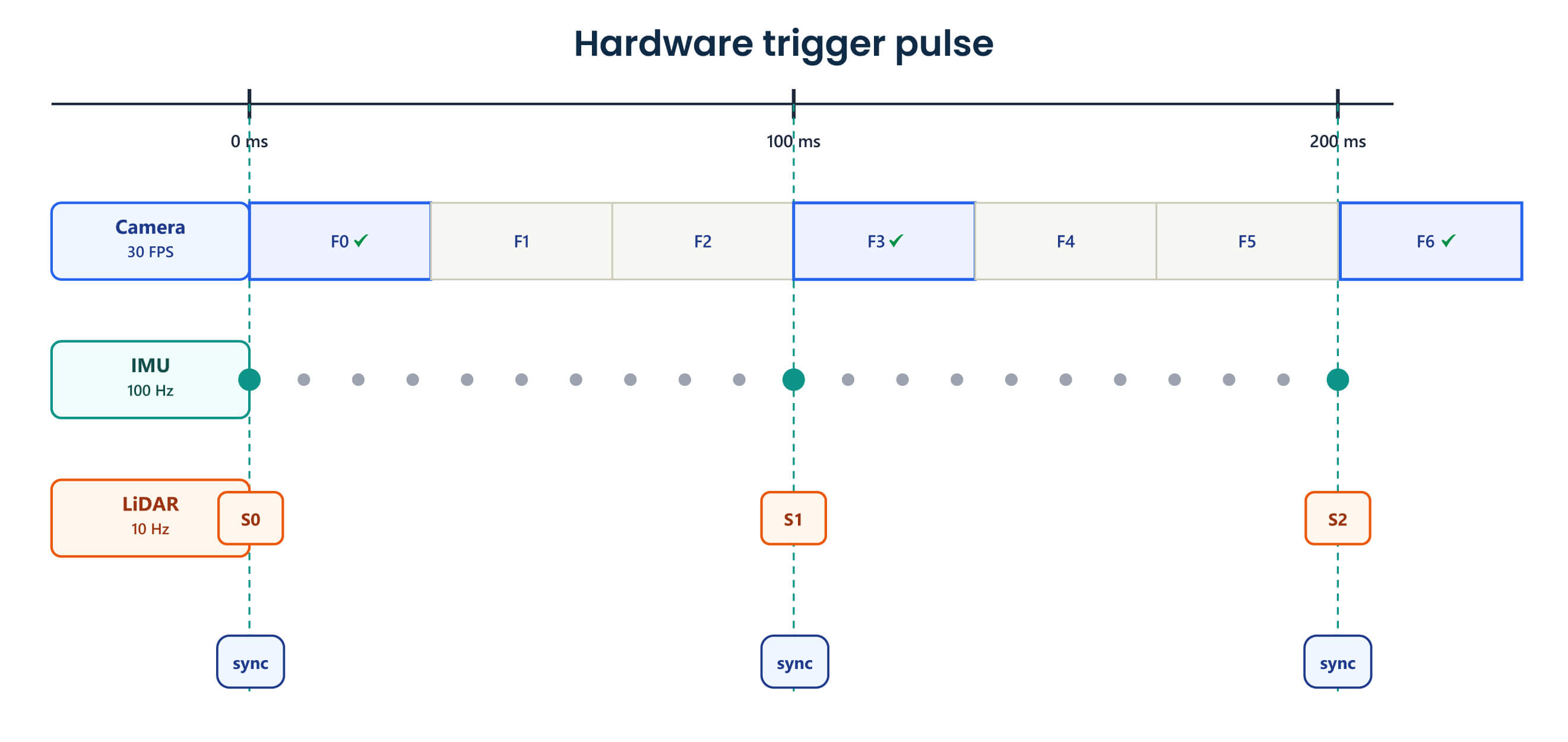 The system then passes the matching data, such as frames 0, 3, and 6, for further processing and discards the remaining data, simplifying fusion across sensors.
Hardware timestamping allows the system to identify which camera frames, IMU samples, and LiDAR scans fall within the same acquisition window and treat them as a synchronized set.
For systems requiring multiple cameras, factors such as camera interface, synchronization method and host platform must be considered during system design. Read our guide on integrating multiple cameras to understand the key considerations.
Synchronizing Multi-Sensor Data on NVIDIA Jetson Orin
The NVIDIA Jetson Orin-based embedded vision platform integrates with the sensors and receives data from all of them within the embedded system.
After data acquisition, the system maps data from each sensor to a common hardware timing reference:
- Camera: Frames received through MIPI CSI-2 are associated with the shared hardware timing reference.
- IMU: Samples received through SPI, I²C, or UART are timestamped against the same timing reference.
- LiDAR: Data received over Ethernet or USB is synchronized using timing protocols such as Precision Time Protocol (PTP). Although each sensor operates at a different frequency, such as cameras at 30 FPS, IMUs at 100 Hz, and LiDAR at 10 Hz, all sensor streams can still be mapped onto a common timeline.
By aligning all data to a common reference clock, the hardware timestamp architecture can seamlessly combine all information from different sensors, enabling accurate depth sensing, localization, and perception in embedded systems.
e-con Systems’ Darsi Pro supports multi-sensor fusion, enabling sensor inputs to be aligned for real-time perception. This unique vision platform also supports up to eight GMSL2 cameras, making it ideal for multi-camera systems.
e-con Systems Offers High-Performance Multi-Camera Solutions
Since 2003, e-con Systems has been designing, developing, and manufacturing embedded vision solutions, from custom OEM cameras to complete ODM platforms. We support a wide range of interfaces, including USB, GMSL, MIPI CSI-2, Ethernet, and FPD-Link, helping to build AI vision systems across automotive, robotics, and industrial applications. We support configurations from single-camera setups to synchronized systems with up to 12 cameras.
Use our Camera Selector to explore our full embedded vision portfolio.
Looking to develop custom scalable, synchronized multi-camera solutions? Connect with our experts by writing to camerasolutions@e-conSystems.com.
FAQs
- 1. What is a hardware timestamp?A hardware timestamp is a precise time value generated by the embedded vision system when the event occurs, using a common trigger source. The hardware timestamp is associated with the corresponding sensor data.
- How does hardware timestamping improve multi-sensor synchronization?
Hardware timestamping captures sensor timing closer to the actual acquisition event. This lets frames, IMU samples, and LiDAR scans map more accurately to a common timeline for sensor fusion.
- How does hardware-assisted synchronization work across sensors with different frequencies?The data received from the sensors are associated with timestamps based on common hardware timing references. The system can then identify frames, data samples, and scans that correspond to the same acquisition window, even when sensors operate at different frequencies.
- What is the benefit of hardware-assisted synchronization for multi-camera systems?
Hardware-assisted synchronization helps align frames from multiple cameras to a common timing reference. This is particularly useful in applications requiring synchronized views from multiple cameras, such as 360° surround-view systems and multi-camera perception.

Prabu is the Chief Technology Officer and Head of Camera Products at e-con Systems, and comes with a rich experience of more than 15 years in the embedded vision space. He brings to the table a deep knowledge in USB cameras, embedded vision cameras, vision algorithms and FPGAs. He has built 50+ camera solutions spanning various domains such as medical, industrial, agriculture, retail, biometrics, and more. He also comes with expertise in device driver development and BSP development. Currently, Prabu’s focus is to build smart camera solutions that power new age AI based applications.