



The recognition of a person by the robot helps to form a more complete understanding of the situation. Although the machine still requires knowledge of the person’s distance and speed as well as its own movement, combining these observations provides the planner with a tracked state against which to base the robot’s response.
This task belongs to perception and sensor fusion.
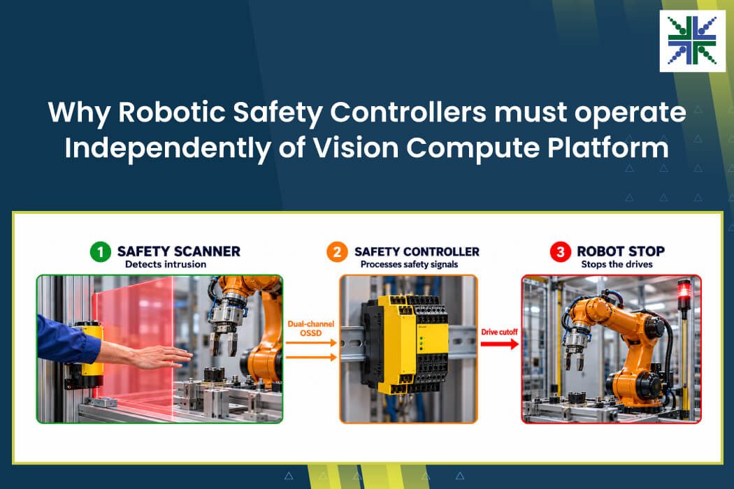
The safety scanner has a separate connection to the safety controller, keeping the camera outside the certified safety function. Understanding that division means examining how sensor data becomes useful for planning and where the scanner departs from that processing chain.
In this blog, you’ll find out how cameras enable robotic perception, the way dual-channel OSSD works, and which fusion stages are outside drive cutoff.
How Cameras Support Robotic Perception
A camera’s contribution begins with the question the application needs answered. Reading a barcode calls for identifying information in a 2D image, whereas approaching a pallet introduces a measurement task. The robot has to locate the pockets and surrounding edges at close range, making depth accuracy central to that operation.
Recognizing scene content and measuring its position place different demands on the image.
Movement adds another consideration to those demands. During fiducial docking, the robot estimates pose as it approaches its target, making global shutter capture important. Barcode capture during travel presents a motion-blur challenge. Maintaining sufficient pixel density across the label and selecting an appropriate exposure time are important for reliable decoding.
In both cases, the image has to retain the information used by the application as the machine moves. Such application-level information then joins measurements from other sensors. A camera identifies what appears ahead, but LiDAR contributes distance and radar measures speed.
These observations reach the compute platform for fusion, where their relationships become part of the robot’s view of its surroundings. The next question is how those inputs arrive and where the safety scanner fits within the hardware arrangement.
How Safety Scanners Connect to Safety Controllers
The carrier board gathers sensor inputs for a shared NVIDIA Jetson Orin NX or AGX platform. Getting camera video onto that board depends on its interface. A GMSL2 camera, for instance, passes video through a deserializer before the data enters the SoC over MIPI CSI-2.
Ethernet cameras and LiDAR reach the platform through the network interface, with CAN, serial and SPI devices connecting through their respective adapters. Although the physical connections differ, their data converges for processing.
At that point, the software still has to turn separate readings into measurements that agree about the scene before using them for navigation and control.
The safety scanner branches away from this arrangement. Its dual-channel OSSD outputs connect directly to the safety controller, which can cut the drives without relying on the SoC or fusion process. This places the stopping action outside the shared compute platform’s work of interpreting sensor data.
Why the Safety Controller Must Remain Independent of Sensor Fusion
Sensor access and timing
Fusion starts with a driver or SDK for each sensor, alongside interface conversion and health monitoring. Those streams need a shared time reference because even correct readings may conflict around a moving object if they describe different moments. A common time base addresses this through hardware triggering for compatible sensors and PTP for Ethernet devices.
Once the streams are aligned in time, their spatial relationships need attention. Each reading has to occupy a common coordinate frame before the system associates it with observations from another device. Intrinsic calibration describes each sensor internally, and extrinsic calibration establishes the relationship between them.
Vibration or impact can disturb that alignment during service, creating a need for monitoring and drift compensation.
Association and state estimation
With the measurements in a common frame, association links readings belonging to the same object. State estimation then combines them with their uncertainty to produce the tracked state supplied to the planner.
For example, the camera detects a person, LiDAR estimates the person’s distance at eight meters, and radar measures their speed at 1.5 meters per second. Fusion brings the observations into a tracked state, with IMU measurements supporting compensation for the robot’s own motion. The planner receives the result of that processing rather than an isolated image or distance reading.
Timing differences, calibration drift, weak sensor input or processing delays may disrupt this fused view.
The scanner-to-controller connection leaves that sequence outside drive cutoff, preserving the separation between robotic perception and the certified safety function.
e-con Systems’ Reliable Camera Solutions for Robotic Systems
Since 2003, e-con Systems has been designing, developing, and manufacturing embedded vision solutions – from custom OEM cameras to complete ODM platforms. We deliver camera solutions based on the imaging tasks assigned to the robot. For instance, we recently empowered a warehousing client with a USB 3.0 camera – based on the onsemi AR0234 global-shutter sensor – for their barcode decoding robot. This addressed the motion blur challenge, which was a major concern.
Use this Camera Selector to browse e-con Systems’ full portfolio.
Ready to discuss your robotic camera needs? Please write to camerasolutions@e-consystems.com and get in touch with our experts.
Frequently Asked Questions
- What information comes from robotic vision?
The 2D images identify scene content, and depth adds location and distance for measurement tasks.
- Where do dual-channel OSSD outputs connect?
They connect directly from the safety scanner to the safety controller.
- Does drive cutoff depend on the vision SoC?
The controller cuts the drives independently of the SoC and fusion process.
- What disrupts the fused view used for planning?
Timing differences, calibration changes, weak sensor input and processing delays affect the combined interpretation.
Suresh Madhu is the product marketing manager with 16+ years of experience in embedded product design, technical architecture, SOM product design, camera solutions, and product development. He has played an integral part in helping many customers build their products by integrating the right vision technology into them.